default

2013-04-01 Cree 40W Equiv. LED Light

I wrote a short blog about the Cree LED lights recently.  Last week I bought two Cree 450 Lm (40W equivalent) LED lights from Home Depot for ten bucks apiece.  The UPC label number is 13959 01932.  I installed one of them in a task light I have over my laptop, which gets heavy usage, more than 3 hours a day, probably 4 or more.  I had been running a Philips 450 Lm LED light in this task light, and it was doing very well, no problems, no flickering, no dimming (see note at end).  BTW, the Cree LED light package says it is dimmable with standard dimmers.

The Cree light bulb looks just like a regular light bulb with a frosted glass globe, but the globe has some kind of coating that feels soft and sticky like plastic, probably to protect it against breakage.  The package says “Safety coated glass”.  The globe has printed on it “CREE  2700k 450 Lumens 6W  | 120V~ | 60 Hz | 50mA”  The white base has a ‘collar’, a ring of fins for heat dissipation.  The overall length of the light is about the same as a regular incandescent.

I installed the Cree light bulb in the task light and turned it on.  The color temperature is only 2700k, which is a very warm light just like an incandescent light bulb.   It flickered slightly, so I checked to make sure it was snugly tight in the socket.  The flickering stopped for a few tens of seconds, but then it flickered once or twice for a second.  The flickering isn’t enough to interrupt the light, but it’s noticeable but not annoying.  It’s intermittent, will not occur for a few tens of seconds, then may occur once or 3 times, then nothing for a while longer.

I have been running the light for the weekend, where it got plenty of use, and on into this week in the mornings and evenings.  It continues to flicker on and off, intermittently.  The times between flickers may be a few tens of seconds to minutes, varying by what seems to be a random length of time.  After a few minutes, just when I forget that it was flickering, it may flicker for a few seconds, then goes back into remission for awhile.  I will continue to monitor this for awhile, and I haven’t opened the second light package, yet.  I’m kind of apprehensive about opening it, for fear that it will also flicker, but I may open it up and use it for awhile to see if it is better.   I think I will eventually take the bad light back to Home Depot and get my money refunded.  If the lights are still out in  the aisle on sale, I may buy a few more.  Other than the flickering, they’re okay, but the 2700 color temperature means they are very much like an incandescent light.

I got to thinking about the flickering, and I thought that it may be possible that the flickering is dependent on the line voltage.  At certain times of the day, it may flicker more when the AC line voltage increases, then when the line voltage decreases, the flickering goes away.  I’ll have to test the light and see if varying the line voltage changes the flickering.  How?  I think I could add a few diodes or a bridge in series with the light to drop a few volts, or even use a resistor.  The power dissipated across a resistor with 50 mA, and 5V is 1/4W, and the resistor would be 100 ohms.  No problem.  I have some 100 ohm 1W resistors I can use.

Update Apr 8 – I connected the LED light to a Variac autotransformer, and varied the AC line voltage from 90 to 130 volts.  What’s puzzling is that now the flickering has gone away.  I was anticipating that the Cree light’s flickering would get worse with a higher AC voltage.  I can think of two reasons why this may be happening.  One is that the autotransformer is causing any line noise to be removed from the AC going to the light.  Another is that I had the LED light plugged into a remote controller.  This is an adapter that plugs into the wall, and is controlled, on and off, by a remote ‘fob’.  This remote controller may be causing the flickering.  But I don’t see how; when I turn the light on or off I hear the remote controller click, which means that it is using a relay to switch the power, not a noise making TRIAC.  I would say that even if it is the culprit, the reason is that the Cree LED light is overly sensitive to it.  I have been using this controller with the Philips LED light for months and have never had any problems with it, so I would not blame the controller, I would blame the Cree light.

Later this weekend I removed the light from the autotransformer and plugged it back into the remote  controller.  I have been using it for several hours and I have not  noticed any flickering.  I’m wondering if it has ‘healed up’ and is now going to act normally without any flickering.  Only time will tell.  But one thing this has taught me: I should (again!) be wary of any low priced LEDs or LED lights, for they most likely obey the old adage that “you get what you pay for”.

Update Apr 11 – I’ve been using the once flickering light a lot, and I now see no sign of the flickering.  It looks like it has ‘healed up’.  The only thing I can think of is there was an intermittent connection somewhere before and now it is no longer intermittent.  I’m hoping it stays that way.

Note: The Philips LED light has a frosted glass globe, but for some reason, maybe heat, the frosting cleared over a portion of the globe, which allowed me to look inside.  The light has a second globe on a pedestal inside, about 20mm or 3/4″ in diameter, colored yellowish orange.  This is apparently the phosphor that converts the light from a blue LED inside of it into the white light.

Update Apr 26 – Quantsuff sent me a link to a short review of the Cree light bulbs.  The reviewer didn’t say much about it, other than the color temperature closely matches the incandescent bulb.  In the time since the last update my Cree bulb has been receiving steady use, and has been flicker free for most of the time.  But occasionally – maybe less than 0.1% of the time, it starts to flicker intermittently.  It happened a few days ago.

Update 2014 Feb 4 – This evening I turned on the Cree LED light and it flashed briefly and went out.  It had been flickering intermittently lately, very seldom as usual.  But this time it went out completely.  I tested it in a known working socket and it would not light, and I put a Pjilips LED light into its socket and it lit okay, so the problem is definitely the Cree.  For certain, it has destroyed my faith in Cree LED lights.  It has worked – even with the flickering – for about ten months, less than a year, and then died.  I think that speaks for the quality.  I have more than a dozen Philips LED lights in service, and none of them have had a single problem.  I should have returned it to the store when I first found that it was flickering.  Oh, well…  Too late now.  All the better, I guess; I’ll have to take it apart and examine it to see what happened.  🙂

default

2013-03-31 Joule Thief Uses Choke For Coil

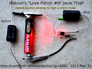
I bought some ‘high current’ chokes from Jameco, P/N 642855, which are 390 uH.  They’re bigger than average, and mount axially; in other words the leads are at opposite ends of the cylindrical package.  They are made by winding relatively heavy copper wire onto a ferrite bobbin.  The bobbin is then covered by a piece of heatshrink tubing (see photo).

Adding Second Coil

I added the second winding, about 5 feet of 30 AWG enameled wire.  I cut off the heatshrink tubing cover and removed 46 inches (117 cm) of wire, and resoldered the end to the lead.  The wire is the kind that the insulation melts away when the soldering iron is applied.  With the wire removed the coil measured 147 uH, a good value for a JT.

I wound about 5 feet (150 cm) of 30 AWG (.25mm) enameled wire over the existing winding, which filled the bobbin up to about level with the ends.  I could have used the extra grooves in the ends of the ferrite bobbin to hold this wire.  But instead I ran both wires through a short piece of green wire insulation, and I wrapped the whole coil with about 4 inches of 3/4″ black electrical tape to hold everything in place.

The Joule Thief

I used a PN2222A NPN transistor, a 1k resistor and a red LED, which happened to be lying on the bench at that time.  I tack soldered everything together to see how it would work.  The red LED lights up very brightly and the JT draws about 125 mA at 1.5V, and runs at 33 kHz.

I named the JT after the song Love Potion Number Nine, which has the words “..it smelled like turpentine and looked like India ink..” because the choke looked like India ink due to the black heatshrink tubing.  It didn’t smell like turpentine as I unwound the wire, but I could feel the wire and tell that the choke was covered with varnish after it was wound, and varnish smells like turpentine as it dries.  These chokes are ‘closeout’ and will very likely not be restocked again after they are sold out.

After building this, I was thinking that it was a shame to waste such a low resistance coil on a regular JT, and I should convert it over to a Supercharged Joule Thief, which takes only a diode and a capacitor.  I looked for some disk capacitors and found a package of 100 assorted disk capacitors that I bought from Radio Shack (cat# 272-801).  I wrote on the back

85 out of 100 “assorted disc capacitors” were marked “561”.  Measured with cap meter, none were above 560 pF.  Most were 530 to 540, some below 500.  Tolerance should be +0, -20%, so measure them before using.

That’s not much of an assortment when 85 percent of the ‘assortment’ is the same capacitor.  So the adage “caveat emptor” applies, here: let the buyer be aware that the package may not be all that it seems.

default

2013-03-30 Joule Thief DC Output Drives Six LEDs

DSC_0236BW2I built this up to see how well the blue LEDs I got recently would work on the DC output of a JT.  I put three pairs of two in series on a perf board and soldered them to the air wired JT.

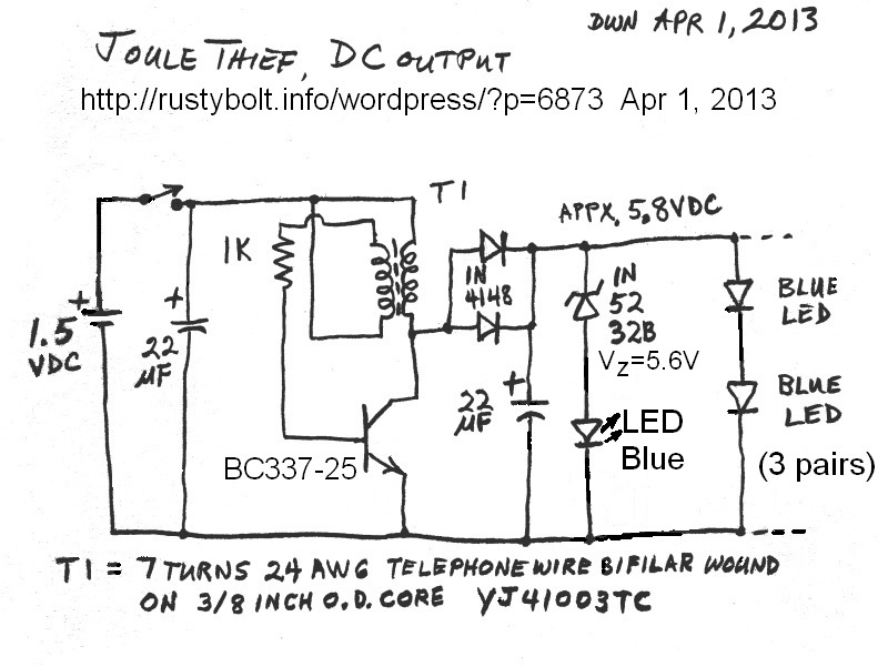
I knew that the Vf of two blue LEDs was going to be more than 6V, so I put a zener diode across the output as protection in case I happened to disconnect the LEDs.  I had a 5.6V zener, but I didn’t think that that voltage was high enough.  I added a regular diode in series with the zener, to boost the voltage somewhat.  The voltage measured 5.75V, which was still well below the 6.6V  that I thought the voltage should be.  So I added a second diode in series, and the voltage went up to 5.79V.  That still wasn’t enough so I added a third diode, but that brought the voltage up to 5.8V.  I knew that I had reached the point of diminishing returns, and adding another diode wouldn’t do anything more.  Theoretically, each diode should have at least 0.6V drop, which should give at least 5.6 + 0.6 + 0.6 + 0.6 or 7.4V total.  I measured the drop across one diode and got 0.42V, so apparently all of the JT’s current is going to the LEDs and almost nothing is going through the zener and diodes.

Looking at the Blue LED Vf

I took one of the individual blue LEDs and connected it in series with a current limiting resistor and to a power supply with a  milliammeter, and a DVM across the LED to measure the Vf (forward voltage drop).  I adjusted the PS for the current through the LED and got the following results for the Vf:

2.5 mA  Vf = 2.90 V

3.0 mA  Vf = 2.93 V

4.2 mA  Vf = 3.0 V

10 mA   Vf = 3.19 V

15 mA    Vf = 3.28 V

20 mA    Vf = 3.37 V

I’m getting 5.8V output from the JT, and there  are two LEDs in series, so the Vf of each LED is about 2.9V.  The above table would indicate that the LEDs are getting about 2.5 mA per LED.  For three pairs that’s about 7.5 mA total.  Not a lot for the usual JT, but because of the higher 5.8V voltage and 6 LEDs, means there’s less power available for each LED.  Multiplying 0.0075 A by 5.8V gives 43 milliwatts.  One uncertainty I have is that I used a fresh 1.5V AA cell for the JT measurements, so I’m not sure what the actual supply voltage was.

I have another brainstorm.  Replace the three series diodes with a LED.  Why not?  I got a whole bunch of blue ones, sooo….  BRB.

I replaced the three diodes with a blue LED.  When I powered it up, the blue LED barely glowed, indicating that almost all of the power is going to the LED array, and only a very small fraction of a milliamp is going through the zener and blue LED.

Back to experimenting…

default

2013-03-29 Ideas For A Mystery Clock

I was reading this web page about the history of mystery clocks and I got some ideas.  One of them I got from my experience with a very old automated voltmeter.  I don’t remember much about this voltmeter other than it used many relays and made a lot of noise and the display consisted of windows, each window ten or more rectangles of plexiglass, each one having one of the digits and possibly a decimal point, and they were all stacked one behind the other.  I think there were four or maybe five windows.  As the number changed, a small light would come on and illuminate the edge of plexiglass for that digit, and the digit could then be seen in the window.

My ideas for this clock are not supposed to be designed for the best visibility or ease of interpretation.  The original round clock with the big hand and little hand was not designed to be easily readable, and we all had to learn how to read it when we were young.  My design is supposed to be somewhat like the original clock.  If had wanted to design it to be easily readable, I would have used four digit windows similar to the four digit voltmeter.

These mystery clocks used the sheets of plastic to hold the minute and hour hands of the clock, so it looked like the hands were suspended in the air, with no apparent means of being moved.  Instead, I thought it would be very cool to have the minute and hour hands etched into sheets of plastic, with each sheet illuminated from the side.

The hour hand would need to have twelve sheets of plastic, each one with the hands positioned around the center similar to the original clock.  Each digit could have the 1 through 12 digits etched at the point where the hand is pointing. Another alternative could be a single sheet of clear plastic with twelve minute hands etched into it, one pointing to each of the twelve hours.  There would be twelve LEDs, each positioned around the circumference, pointing to each of the twelve hour hands.  But I’m not sure that there would be enough isolation between the hands, so it might look like there were three or more hands illuminated instead of just one.  A solution to this might be to etch a deep line betwen the hands and fill it with black paint to block the light.

The minute hand would have to be much more complex, it would require 60 sheets, one for each minute, or a single sheet with sixty hands etched into it.  I think the stack of sheets would be too thick for the clock, or it would be impossible to illuminate just a single minute hand.  So instead I thought that it would be better to have two windows, one with six sheets, 0 through 5 on the left, and 10 sheets, 0 through 9 on the right.  Then the minutes 0 through 59 could be indicated with only 16 sheets.  There could also be a sheet for AM or PM, or else the LED color could change from yellow for AM to blue for PM, for example.

Instead of stacking the minutes digits one behind the other, they could be two rows, the top row with the digits 0 through 5, and the bottom row with the digits 0 through 9.  The rows could be below the clock face, or on the side, arranged as columns, either both columns on one side or one column on one side, the other on the other side.  But I’m not so sure this would be as easy to read as both on one side.  The problem with the columns is that it would be less symmetrical than the rows at the bottom.  Perhaps it would be a good idea to add two more ‘digits’ to the tens of minutes column for AM and PM, making a total of 8.

I know that the easy route would be to just put a third row of 12 more digits for the hours and skip doing the clock face.  It is really tempting to go this route.  But in this case technology must not triumph over art.

The Electronics

There could be several different ways to decode the time to get the power to the LEDs.  One, most straightforward, would be to use some decimal decoder chips, one for each digit.  The driver could be a microcontroller chip with a precision crystal oscillator for accurate time.  Or the clock could use a dedicated clock chip, but the output might be in seven segment, which would require further decoding.  Another way could be to use a quartz clock movement for the precise timing and replace the mechanical part with a resistor, and use the 1 second pulses for the clock.  The microcontroller could sense he pulses and advance the time.  I don’t think the circuit would need to be multiplexed because there is no need to minimize the pins on any display.  The displays are just LEDs, and all that is needed are registers and decoder chips.  When I think about it, the clock only requires counters, not a microcontroller, because there are no decisions that need to be made.

default

2013-03-28 Built Several Germanium Joule Thiefs

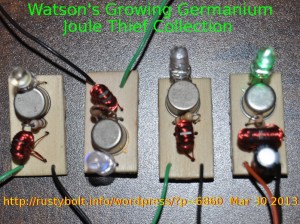
I went on a Joule Thief building binge for a few hours last night, making up some germanium Joule Thiefs after I found a small box of old unidentified germanium transistors that I had forgotten about.  I used a small piece of the “Woodsies Squares” thin birch plywood about 1/2″ by 1″ (12.5 by 25 mm) that I got from the crafts store.  I used the #60 wire size drill in a General #92 pin vise to drill the holes to mount the parts.  The PNP germanium transistors had barely visible remnants of labels on the top; might have been Texas Instruments symbols.

I got some of these transistors in a lot I bid on on eBay, for a very low price if I didn’t count the shipping (the seller, apparently not knowing what they were, called them resistors).  The transistors are apparently from the first decade of the transistor, probably late fifties to early ’60s.  They measured low gain, so I used a lower value resistor, 390 ohms for one JT, 470 and 560 ohms for the others.  I haven’t completely assembled the third one, which will probably have another 470 ohm resistor.  I had several germanium JTs working, but none were neatly assembled on a board, they were just tack soldered together.

I used T231212T cores from Surplussales.com, with three conductors of 30 AWG solid enameled wire, about 6-1/2″ (17cm) long wound trifilar.  I paralleled two of the three to make the primary and the remaining single winding became the feedback winding.  What really has me puzzled is why I had such a large discrepancy in the three coils I wound.  All three cores were pulled from the same bag.  I wound all three coils identical, with about 6-1/2 inches of the same 30 AWG wire, trifilar.  They all had about the same number of turns.  Two of the coils measured 105 to 115 microhenrys, while the third measured 440 uH, almost four times higher.  My thoughts were that the seller had dumped more than one type of core into the same bag and mixed them up, so that they were actually selling two (or more) different cores as the same part number.  Or another theory might be that the manufacturer was selling this as floor sweepings or rejects, and the seller was hiding the fact that the parts were not new.  Whatever the case, I may have to go through the whole bag of them and test each one, because I have several dozen still left in the bag.

This morning, Mar 29, I dumped a bunch of the cores out and started measuring each one by slipping a short length of resistor lead in the clips of the LC meter through each core.  This single turn measurement showed about 2 to 2.5 uH for most of the cores, but there was a pile of 20 or more that were ‘substandard’, many measured below 2 uH, some between 1 and 1.8 uH.  Those were definitely out of tolerance so I bagged them separately and labeled them rejects.  They’re okay for a Joule Thief, they just have lower inductance, that’s all.  But still the seller gave the specs and these rejects clearly don’t meet them.

In the picture the second from the left LED is glowing dimly, and the far right green LED is lit up brightly.  This is connected to a Rayovac ‘Heavy Duty’ C cell that was purchased almost 25 years ago.  Before I put it on the JT, it measured 1.52 V, less than when it was when new, but still good for lighting up the JT’s LED.

default

2013-03-25 Germanium Transistor Guts

P1030353S2I took this picture by holding a two lens pocket magnifier in front of my point-n-shoot camera.  I came out good considering that the magnifying lenses had no color correction.  That’s why there’s a slight color fringe at some dark and light points.

This is an old germanium transistor from the late ’50s or early ’60s made by Texas Instruments.  I filed off the edge around the case and pulled the cap off.  The diameter of the whole disk is about 1/8″ or 3mm, which is huge by today’s standards.  Today they could get a whole microprocessor in that size disk.  The actual transistor chip is the inner disk, and this disk itself is the base of the transistor.  The bond wire from the ‘post’ comes over and goes into the blob in the center of  the disk, which is the collector.  The other side has one that looks almost the same, but it is the emitter.

Germanium has to be put into a hermetically sealed package because the germanium cannot be passivated like silicon.  Silicon can be passivated by changing the surface to silicon dioxide, or glass.  Then epoxy or plastic can be put over the silicon chip.  The first germanium transistors were packaged in plastic, but they went bad as the moisture in the air seeped up through the space between the plastic and the wire leads.  The manufacturers then changed to a hermetically sealed metal package.  In this case, the metal base, shaped like an upside down pan, is filled with glass, which seals the leads where they go through the glass.  Nothing could get through the case once the lid was welded on.  I removed this cap years ago, so the chip has been exposed to moisture and air and has most likely quit working shortly after it was removed.

default

2013-03-24 Two Transistor “JT” Uses Inductor From CFL

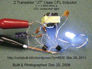
I put this together during the Xmas holidays back in 2008.  It may have been posted to my watsonseblog, I don’t remember.  But here it is for the world to see again.

It’s the typical 2 transistor voltage boost circuit – often mistakenly called a Joule Thief – with a BC337-25 for the driver transistor.  I used the choke or inductor from a defective CFL light bulb.  The two transistor circuit allows the use of a coil with a single winding.  The DC resistance of this choke is high which reduces the output and decreases the efficiency, but it puts out some light, as can be seen in the photo.

I see that the 100 pF “102” capacitor has a paralleled pair of 22k resistors (equal to 11k) in series.  Recently I put a 10k or 25k trimpot in series and adjusted it and noticed that the LED gets brightest at some point of a very broad peak.  Apparently this resistance makes the current pulse broader, and there’s a point where it’s at an optimum width.  This resistance, the capacitor and the inductor influence the circuit parameters that determine the frequency of the circuit.

default

2013-03-23 LED Brightness Comparison

I did learn something from the Grease Spot Photometer Experiment.  I found that the grease spot really does work.  I can compare the brightness of two LEDs to find out the current in each LED.  But then I realized that I don’t really need two LEDs (I didn’t use two with my luxmeter measurements).  All I have to do is use a single LED, and switch it between  the Joule Thief and a known adjustable current source.  When I adjust the current source to give the same LED brightness then I can read the actual current from the source.  This is the system that I built.

Background

A few years ago I built up a measurement jig to use my then new luxmeter as the instrument to compare the LED brightnesses.  I cut a small hole in the end of a small cardboard box and I fastened a LED into it so that the LED’s light beam was hitting the far side.  I then cut out a large hole in the far side to allow the luxmeter’s sensor to be placed there to measure the LED’s light output.  I used this not for comparison, but  for actual LED light output.  But I really don’t need to have an absolute measurement of the LED’s light output.  All I need is a comparison of the LED light output from the JT and then from a current source.  The important part is that both use the same LED and photocell, so the measurements will be the same.

The Box

I will use a single LED, so I need to switch it between the JT and the current source.  I used a SPDT switch, and I put a 5.6V zener diode across the wires from the JT so that when the LED was disconnected from the JT, the excess voltage would be dissipated in the zener diode.

I didn’t want to use the luxmeter, which eliminated the cost and difficulty in obtaining it.  Instead I wanted to use a cheap DMM,  And to make it easy, I used a CdS photocell from Radio Shack (276-1657). To keep ambient light away from the photocell and skewing the measurements, I chose a cardboard box

I drilled two 5mm holes for the white LED in the end of a cardboard box[1], and on the other end I drilled two small holes for the leads of the photocell, passed the leads through to the outside and soldered a short flexible pair of wires to it for the meter clip leads.  I wanted the LED to fit through the hole without moving around, so I drilled two 5mm holes side by side in a small piece of thin plywood and glued it to the end of the box, over the two holes.  This gave the LED a firmer fit than just the cardboard.  I wanted the whole jig to be stable so that measurements would not change due to position changes or movement.  I left the CdS photocell leads free so I could clip on my DMM.  I should have added a second switch to switch the DMM leads, but for now it’s working okay the way it is.

I soldered  the switch to the LED, a 100 (actually 98) ohm resistor, and a 5.6V zener diode.  I used a Joule Thief circuit I had laying around, removed the LED and soldered the switch leads to the where the LED used to be.

Measurements

I connected the 1.5V supply to the Joule Thief circuit.  With the switch set to connect the LED to the JT, the DMM measured 7.4 millivolts across the 0.47 ohm resistor that was already in the JT.  7.4 divided by 0.47 gives 15.74 milliamps through the resistor.  That’s about what should be expected from a conventional JT.  I measured the photocell and it was 1902 ohms. I then switched the LED to the power supply and adjusted it until the DMM read 1894 ohms (it was very touchy and hard to adjust).  The LED was now putting out the same amount of light as it was from the JT.  I measured the voltage across the 98 ohm resistor and got 1.29 volts.  That, divided by 98, gave 13.16 milliamps through the resistor and LED.

Conclusion

The LED driven by the JT measured 15.74 milliamps across the 0.47 ohm resistor.  The same LED putting out the same amount of light measured 13,16 mA on the power supply.  The JT reading across the resistor in series with the cathode was 19.6 or about 20 percent higher than reading the LED driven to the same brightness by the DC from the power supply.

Others questioned the accuracy of using a current sensing resistor in series with the LED, and a DMM to measure the LED current.  They said that the DMM could not accurately measure the pulses of current through the LED.  I agreed with their assertion, but I said that the measurement gave a good relative reading of how the circuit was performing.  Now I can say that the DMM measures about 20 percent higher than it should, and if further measurements with other JTs confirm this, it could be applied in general for any JT with a DMM.

Another One – Mar 23

I put another JT on the jig and made measurements.  This JT used a PN2222A transistor, a 1k base bias resistor, and 5 turns 24 AWG wire bifilar wound on a 3/8 inch (9mm) high mu core.  The 1 ohm LED resistor measured 15.7 mV, which is 15.7 mA.  The photocell resistance was 2091 ohms, and it took 1.128 volts across the 98 ohm resistor or 11.5 mA to get the same photocell resistance.  The 15.7 mA divided by 11.5 mA gave 1.1365 or 36.5 percent higher for the 1 ohm current.  That was quite a bit more than the 20 percent earlier.

Mar 24 – #3

This one was a Supercharged Joule Thief and I used a trimpot in series with the 1k resistor.  This allowed me to adjust the V drop across the 1 ohm resistor to 20 mV, which I later measured at 20.1 mV, same as 20.1 mA.  I completed the other steps and the result was 14.17 mA DC.  Then 20.1 / 14.17 gave 1.418 or 41.8 percent higher.  This is the highest so far.  I do not know if being a Supercharged Joule Thief had anything to do with the results.

More to come.

[1]] The cardboard box measured 11 inches (275mm) long by 6.4 inches (163mm) wide by 2.75 inches (70mm) high.


default

2013-03-22 LED Vs LED In Grease Spot Experiment

I thought about doing this since I wrote a blog on it back in the mid 2000s.  Use the Grease Spot Photometer Method to compare the outputs of LEDs.  This experiment is used in Physics classes to demonstrate the relationship between candles and the distance to the light source.

In my case I decided that I should connect two white LEDs fresh out of the bag in series, so that the current through them is identical.  I put a 100 ohm resistor in series so I could measure the voltage across it and calculate the current.  For every volt, I would get 10 milliamps current.

I soldered the two LEDs onto the ends of half meter lengths of thin flexible stranded wire.  At first I was going to use some old speaker wire I had, but I changed my mind and used some twisted pair from a cat5 patch cable.  Some short lengths of shrink tubing helped to prevent things from shorting out.

I dropped a drop of shredder oil in the middle of a quarter sheet of paper.  I could have used grease, butter, lard, salad oil or similar.  I spread the drop out until it was about 30 or so millimeters diameter, then I blotted the excess oil away with a sheet of paper towel.  The oil tends to spread out over a few days, so I may have to make up a new sheet periodically.  I used a spring clamp to hold the paper up while it was resting on the floor.  I put a yard/meter stick on the floor next to it, with the paper at the fifty centimeter point.

I connected up the LED assembly to a power supply and adjusted the voltage to give 2 volts across the 100 ohm, which was 20 milliamps LED current.  Wow, nice bright beams from the new LEDs.  The power supply voltage was 8.58 volts or about 3.3 volts per LED.

I held one LED left of the paper at the 30 CM point, which was 20 cm from the paper.  I then held the other LED right of the paper at the point where the grease spot disappeared when the beams were pointed at it.  I looked at the right LED’s distance and it was at 71.5 cm, or 21.5 cm from the paper.

What this small difference means is that the right LED has as slightly brighter light output for the same current as the left LED.  But the main point is that it shows that this grease spot method does a reasonably accurate job of comparing two light sources, and the cost is almost nothing.

What I need to do now is add a switch so that I can switch one LED over to a Joule Thief and be able to compare its light output with the the other LED’s current, which will be adjustable by varying the power supply voltage.  I also need to make sure that the grease spot disappears as the current to the two LEDs is varied over a range, say 5 to 25 mA.

I plan on mounting the paper and LEDs inside of a box to keep out the ambient light.  I will have the LEDs fixed so that the grease spot disappears when their current is the same.  Then I can switch one LED over to the Joule Thief and compare  the light output from the JT with the LED connected to the adjustable  power supply.  When they are the same, I can then measure the voltage across the resistor, and get the actual current through  the LED.  Because the light output from both LEDs is the same, I can assume that the JT is putting the same average current through the LED.

Another method

I bought a Luxmeter a few years ago and it also works for this comparison.  I thought about another method.  Instead of comparing two LEDs, I could use the same LED.  I would need to connect it to a DPDT switch or relay to allow me to switch the LED between the power supply and the JT.  The currents would be equal when the LED does not change brightness when the switch is changed.  If I don’t trust my eyes to make that judgment, I can aim the LED at a CdS photocell and measure the resistance of the power supply and JT, and if the two resistances are the same, the two currents through LED should be the same.

default

20123-03-21 Joule Thief Runs On Broken Toroid

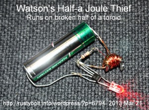
I had some short lengths of wire laying around, a 1k resistor, a red LED already soldered to a transistor, and this half of a broken toroid.  After a few minutes of fiddling, the result was this working Joule Thief.  It shows you can make a JT that works from just about anything even if it’s half gone.

© RustyBolt.Info/wordpress
CyberChimps