default

2013-04-12 Joule Thief With a Xmas Tree LED Light String

One of my email correspondents, Paul, has built a baker’s dozen of the Joule thiefs with LED light strings, but all were white LEDs.  I have a few strings of Xmas tree LED light strings, but all of them are multicolored, and are the type that run off a battery pack of four AA cells.  I already knew when I bought these that they were a poor choice, because a co-worker had tried one and found that the batteries only last a few days to a week.  Naturally, there are twenty LEDs in parallel and if you run them at ten milliamps apiece, they draw 200 mA and eat up a battery in no time flat.  But I bought them knowing that I would abandon the batteries and use them on something else, like a power supply or solar panel.  I also was curious as to how they managed to get the different colored LEDs to light up without the lower voltage ones hogging all the current from the higher voltage ones.

Paul’s string of LEDs has them also in parallel, but since they’re all white, there is no voltage mismatch, and they should all light about equally.  To my eyes, my string looked like the blue LEDs were somewhat dimmer than the others, which would be expected since they are higher forward voltage than the other colors.  This string uses 3mm LEDs, and I don’t see any bulges in the shrink tubing covering the wiring, which in my mind should be logical: resistors can be used to even out the LED brightness by reducing the current to the lower voltage LEDs.  But the makers seem to be too cheap to add the resistors, so I’m not sure why the red and orange LEDs don’t hog all of the current.  Maybe they’re special LEDs with a resistor inside of the case.  I opened the battery box up and there is a single resistor inside, it’s low value but I don’t remember what the value is.

I poked around in the battery box and found the two contacts that powered the LEDs.  I clipped them onto a Joule Thief that had been modified.  I added a 100k logarithmic taper pot in series with the existing 1k resistor, so I could vary the brightness of the string.  The transistor was a BC337-40, which is high gain and really requires a higher resistance than 1k.  I powered the JT from a power supply set at 1.5V, and it drew about 200 mA with the pot set to its minimum.  The LEDs were bright.  I then adjusted the pot to give about 100 mA of supply current.  Most of the LEDs were still bright but the blue ones were noticeably dimmer than the other colors.  I increased the pot and the blue LEDs dimmed out completely, but the other colors were still lit.

This was what I expected, since I could not find any balancing resistors as I said above.  I adjusted the pot back to a supply current of about 100 mA, and the LEDs looked okay, even though they were not all the same brightness.  I removed the power and measured the resistance of the pot and resistor and they came to about 2000 ohms, so I unsoldered the wires, 1k and pot and put a 2k resistor in there.  When I restored power , the LEDs were lit up the same as previously, and the supply current was about 130 mA (the power supply’s 1 amp analog meter is low resolution).


default

2013-04-11 A Complete history of Mainframe Computing

I found this link to a slide show called A Complete history of Mainframe Computing by R. Arzoomanian.  The pictures are fantastic. I thought this tidbit was very remarkable: “In fact, by the time it was retired in 1955, it was estimated that the ENIAC by itself did more calculations than all of humankind did up to 1945.”

However I have to take issue with some of what the author says and claims.  First off, I use as my reference a book called “Bit By Bit An Illustrated History of Computers” by S. Augarten.   Some things Mr. Arzoomanian says are actually errors, such as when he claimed that the ENIAC cabinets were 49 feet high.  Perhaps he meant 49 feet long.

The author calls them the “two heroes”, but gives their names as Mauchly and Presper, which is his first name, not his last name, which is Eckert.

But I take exception to the claim that he makes over and over that the vacuum tube computers were unreliable.  Yes, they used a lot of heat producing tubes.  But the engineers early on learned that if the plate voltage was reduced, the lower power meant a greatly increased lifetime.  Also, the operators ran tests on the computers during maintenance time, and if they found a problem with marginal tubes, they fixed it, so during regular operation there were very few problems with the computer.  Referring to tubes, the author said,

“However, they used a lot of power, got very hot, and were very unreliable. These were tradeoffs he and others had to live with and were unfortunate characteristics of the computers built from them.”

He uses the word very twice and the word unfortunate, and I have to take him to task for that.  He failed completely to say the one positive thing about tubes (valves), and that was they were not subject to the physical limitations of mechanical devices and could operate at speeds far exceeding mechanical relays, and so ushered in the advent of the modern electronic computer.  Without tubes we would not have had the opportunity to develop the hardware and most importantly the software that modern computers use.

In the comments, someone brought up the computers that Konrad Zuse made in Germany during the war.  The early generations of Zuse’s computers were electromechanical, they used relays, not tubes.  The relays were much slower and somewhat prone to errors if they were operated too quickly.  Zuse used 35 mm film for the punched tape.

In the last decade, the British declassified information about Colossus, the computer they used for deciphering the German encrypted radio messages.  This was kept a secret for over fifty years, and only recently have they claimed that the Colossus was the first electronic computer. Mr. Arzoomanian had the audacity to call his document “The complete history..” but he totally forgot to even mention this and several other mainframe computers.  We ran a Honeywell Bull mainframe for decades, and used it with PC or IBM Plug Compatible (Bus and Tag) peripherals.  He also didn’t mention that his “heroes”, Eckert and Mauchly, lost in court to Atanasoff’s ABC computer when it was determined in court that Atanasoff had built the first computer, not Eckert and Mauchly.

I have to thank the author for showing all those old pictures of mainframes, because most people have never seen this important part of computer history.  But I highly recommend that the reader take this document with a large number of grains of salt, and refer to a more accurate document such as that which I referred to at the beginning.  A good place to start would be Wikipedia.  After reading the remaining photo descriptions, I then saw that the author was working in the IBM mainframe environment and it’s obvious that he would be biased towards that brand of mainframe.


default

2013-04-10 Pic Of One Of My “JT” Flashlights

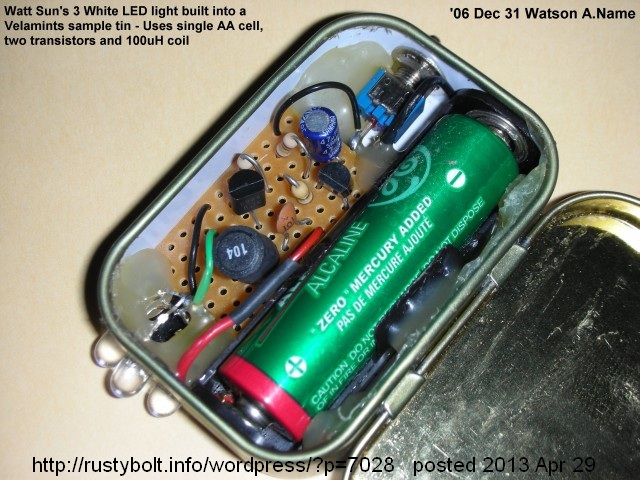
DSCN0591SHere’s a picture of one of my flashlights, taken on the last day of 2006.  I most likely had this posted on my late great watsonseblog.  Maybe even here, too.

default

2013-04-09 Supercharged Joule Thief Schematic and Parts List

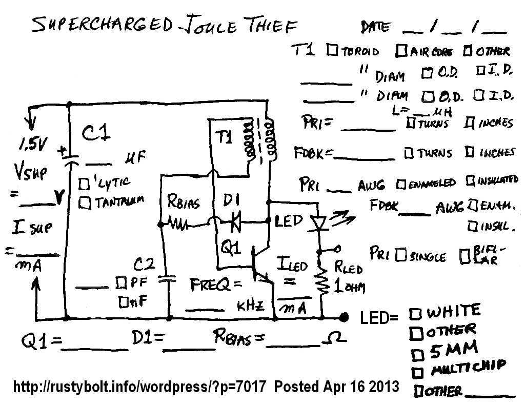
DSC_0265S3I drew this schematic up a few years ago (2009, IIRC) when I first made the Supercharged Joule Thief.  It was supposed to help me keep track of the several SJTs that I built, and continued to build to validate the design.  I suppose I should delete all of the text in the schematic, and put that text in a full sized sheet of paper with the schematic in the upper right corner.  But that takes a lot of time and I’ve already spent the better part of an hour just getting it to where it is now (no thanks to Irfanview, which keeps on crashing when I use it in Win 8).  Maybe later…

default

Protected: 2013-04-08 SAC’s Hewlett Packard Minicomputer

on April 8th, 2013 by - Enter your password to view comments.

This content is password-protected. To view it, please enter the password below.

default

2013-04-07 Garage Door Open Alarm Prelims

Wanna Make A Garage Door Open Alarm

This is a continuation of my previous blog.  I could use two 555 timer chips in the astable mode to generate a European type siren with the high-low ‘warble’ tones, but I decided I would do it with a couple transistors.  Actually I coul+d use a single 556 dual timer chip, but that’s not commonly available.  I’m trying to make an open garage door indicator warning siren, optionally with a light.  What I will have is a reed switch with a circuit and a few batteries to run it.  This will be located in the rafters in the garage ceiling so that when the door is open the magnet on the door will close the reed switch.  The reed switch will then connect the batteries to the circuit.  The circuit will then transmit a radio frequency signal on about 88 MHz, consisting of the RF carrier, modulated with the high-low warble tones.  The radio in the house will be tuned to this frequency, and when the door is closed, it will be silent.  When the door is opened, the radio will then sound the alarm sound, alerting me that the garage door is open.

I don’t have to use a reed switch, but I have a lot of them that I salvaged from old phones.  They were used to detect when the  handset was in the cradle, so basically they were the same as the switch hook.  In all the years that I worked on the phones, I never saw a reed switch go bad.  More than a dozen times there were complaints that the phone would not hang up.  But in all cases, the problem was that the user had dropped the handset on the floor or table, and the magnet, being heavy, came loose and moved away from its proper position, causing the reed switch to stop closing.  Replacing the handset always took care of the problem.

I thought about using a Microswitch instead of the reed switch.  The Microswitch is like the ones for the mouse buttons but bigger.  They are small and have holes for mounting to something solid.   Some even have a metal tab that sticks out to make contact with a door or whatever.  I could also use a magnetic alarm switch for a window.  It’s basically  the same thing, a reed switch and a magnet.

Back to the G. D. Open sensor

I observed the garage door, which is a roll-up type, as it traveled in its tracks.  One problem I see is that it wobbles a lot, and stops at a place that may vary by a good fraction of an inch, maybe as much as a half inch (12.5mm).  It also may vary its position in the track, so the combination of the two variables means that if I mount a magnet on the door, and a reed switch on the structure, it must work with the magnet as close as almost touching, or as far as an inch away.  I see a problem with this, as the reed switch may not close when it’s so far away.  I came up with a couple alternatives that might be better.

One is to mount a mercury tilt switch on a pendulum that gets moved several inches when the door is open.  The position of the pendulum would not matter as long as it was past a certain point.  But the mercury switches are very difficult to obtain because mercury is considered a hazardous material.  And it could be very expensive.

Another solution involves the use of a LED and photocell to make a light beam sensor.  One way would be to put the LED on one side of the door and the photocell on the other side.  When the door is open, the beam would be interrupted and the alarm would go off.  Another way would be to mount both the LED and photocell on one wide of the door, and put a reflector on the door or use a shiny metal spot on the door to reflect the light.  When the door is opened, the reflection would turn on the photocell.

One problem I see with this sytem is that there is a continuous demand for current to light the LED, so using batteries is not economically possible and since the stuff is located up in the garage ceiling,  it would mean a climb on a ladder to replace the batteries every few weeks.  I’d like to avoid that if possible.

Another use

Another useful tool is the wire tracer.  I have one of these the little box that clips on to the pair of telephone wires and sends the “deedle-deedle-deedle” tone down the wire, so it can be traced by the probe.  I could put this circuit into a small box with a pair of clip leads and m,ake one just like the commercial models that sell for $30 or more.  I really don’t need to. because I picked up a genuine “Bell System 139B Test Set” at a swap meet, and I took it apart and fixed the intermittent contact problem with the battery holder.  That’s one thing that will really make a person angry.  I use the tone tracer box at work to find a telephone line among the hundreds or thousands of others.  One end may be located a thousand feet away on the other end of campus.  If I put the tone tracer box on the phone line and walk all the way down to the other end of campus and can’t find the line because the box stopped working, and I have to walk all the way back to fix it, then walk all the way down again, it can get really frustrating.


default

2013-04-05 Pulse Generator, Two Transistor, Variable Frequency

I assembled the circuit to see if I could come up with an alarm.

Wanna make an Open Garage Door Indicator Alarm

P1030367BW4

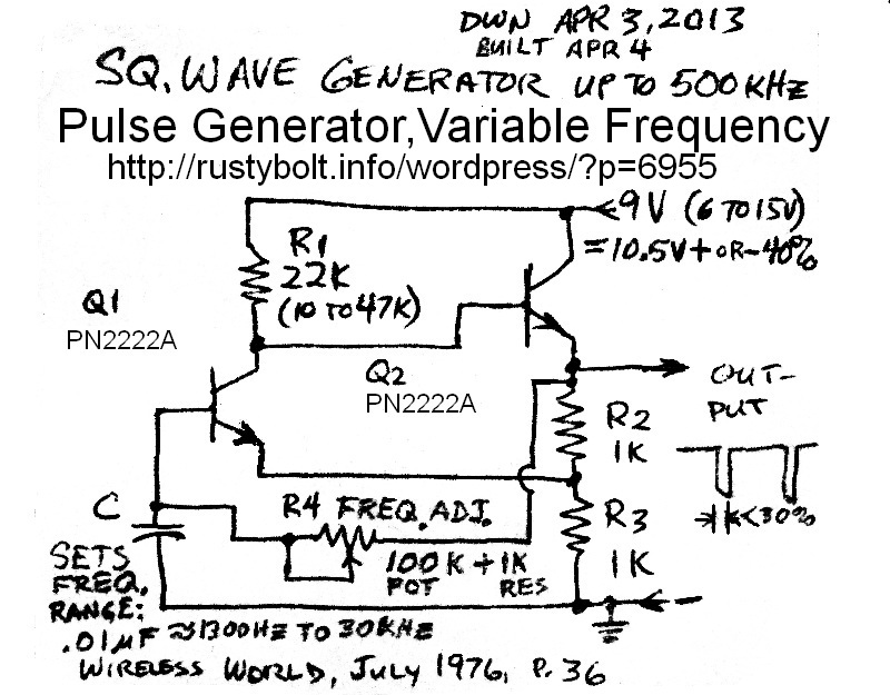
The circuit uses two transistors in a circuit that needs only a single timing capacitor and timing resistor to determine the frequency.  It’s somewhat similar to the flasher circuits I’ve been working on, but it uses 9V supply voltage.  It could be as low as 5V, or maybe even lower, but I figure that the alarm will only be on for very short periods of time, a 9V or 6V battery should last for a very long time.

The circuit will be two of the pulse generator circuits, one running at mid audio frequencies, and the other will be running at a pulse every 1/3 second or so.  This will vary the audio pulse generator up and down.  Then that output will be used to frequency modulate the RF generator.  I know how to do that, but I’m not yet sure where the 1 second pulses will be fed into the audio generator to vary it up and down.  I may connect it through a high value resistor to the base of Q1.  The change in frequency doesn’t have to be a lot, just enough to make it distinctive and easy to recognize.  Maybe a few hundred Hertz will be enough.

I built up the circuit in the schematic above, and it worked good.  I could vary the frequency from 1300 Hz to 30 kHz.  I touched the base of Q1 with my finger while I was connecting the scope probe, and I noticed that the scope showed the frequency was being modulated by the 60 Hz hum from my body.  Apparently the circuit is sensitive at that point and I should be able to feed the slow pulse generator into that point through a resistor and get it to vary the audio tone.

I have also been thinking about how to use a lower battery voltage.  I could feed the 1.5V battery into one of the flasher circuits, and use it to boost the voltage up to 3 or 4 volts.  I could also use a Joule Thief to boost the voltage up to 6 or so volts, and run the whole circuit off that.  This method seems very attractive, since I have most of the stuff already laying around.  The only question is will the output have enough current to run the RF section and the pulse generators?  I’ll have to check out the current drains.

Of course the single circuit without the warble can be used to do whatever a 555 timer chip can do in the astable mode.  The 555 made it so easy to just put the chip into a circuit, that the Real Engineers all forgot how to do it with a simple  two transistor circuit like this one.  It’s probably cheaper, and probably isn’t much different in the number of parts and ease of building.  Once you get to know how the different values of R and C interact in the circuit, it should be easy to guesstimate the approximate value of the timing capacitor and resistor.

Warble Circuit

I clipped a 120 ohm earphone element from a telephone handset to the output.  I could adjust the frequency from  I clipped a 10 uF electrolytic capacitor across the .01 uF, and measured the frequencies.  I could vary the pulse rate from 1.25 Hz at the pot maximum, to about 30 to 40 Hz near the pot minimum.  I’m guesstimating that a frequency somewhere around 3 Hz should be a good warble sound.

Another use(s)

Another thought that I had was to make a subcarrier.  I could set the frequency of the pulses at some high frequency above the audio band, say 38 kHz.  Then I could put a microphone with a single transistor preamp on the pulse generator and generate a frequency modulated carrier.  I could feed this into a red LED and send the audio modulated carrier on a light beam.  I could also use it to  modulate the RF carrier, and that would conceal the audio, so it could not be heard until someone used a subcarrier demodulator to recover it.

Another useful tool is the wire tracer.  I have one of these, the little box that clips on to the pair of telephone wires and sends the “deedle-deedle-deedle” tone down the wire, so it can be traced by the probe.  I could put this circuit into a small box with a pair of clip leads and m,ake one just like the commercial models that sell for $30 or more.  I really don’t need to. because I picked up a genuine “Bell System 139B Test Set” at a swap meet, and I took it apart and fixed the intermittent contact problem with the battery holder.  That’s one thing that will really make a person angry.  I use the tone tracer box at work to find a telephone line among the hundreds or thousands of others.  One end may be located a thousand feet away on the other end of campus.  If I put the tone tracer box on the phone line and walk all the way down to the other end of campus and can’t find the line because the box stopped working, and I have to walk all the way back to fix it, then walk all the way down again, it can get really frustrating.

I continue this in my following blog.

default

2013-04-04 Removing Toroid Cores From Epoxy Potting Compound

In 2009 we decommissioned the old PBX system after replacing it with a Cisco VOIP phone system.  Most of our campuses just got rid of the equipment lock, stock and barrel, but the whole room full remained at my campus.  Over the years, I retrieved a few of the boards, each one about 16 inches square with 24 circuits handling 24 phone lines.  The boards connected to the central office had 24 circuits that looked like an analog telephone to the C.O.  These used a hybrid transformer with four 600 ohm windings (more about them here).  The boards connected to the telephones furnished power and put out a digital signal to the phones.  These used a ferrite toroid core transformer to isolate the line from the circuitry. These high permeability cores made excellent Joule Thief coils and were good for many other things.

Removing one from the board was very difficult because the eight pins absorbed most of the soldering iron heat, so I yanked them off with a vice grip pliers,.  Each of the 24 transformers had a half inch O.D. ferrite toroid core encapsulated in epoxy.  Needless to say, this made them very difficult to get out of the case.  I did a few with a hammer and screwdriver, but I broke about 1 in 4 cores,  With scores of the cores gathering up, I had to find a better way to remove them from the case.

In late 2010 I took a few outside and used a propane torch to burn them to charred remains.  I figured that since the ferrite core, just like the Hobbits’ One Ring, was born in the fire, the heat from the torch couldn’t hurt it.  After removing them from the charred remains and removing all the wiring and washing them, the cores came out unscathed and ready to serve as very good JT cores.

But the torching took tens of minutes and the nasty smelling smoke and fumes were blowing in my face.  I did about one board of 24 cores this way, but I was looking for a better way.  While I was at the hardware store looking at some clear polyurethane coating, I checked out some paint stripper on the shelf.  It said that it would strip epoxy, but that was paint, I thought, and it might not work on a cube of solid epoxy.  But I decided to give it a try.

I used a pint (473 ml) glass jar with a steel lid, and dropped a few of the transformers into it and covered them with a glob of the stripper.  The stuff is viscous, so that it will stick to a vertical surface while it’s dissolving the paint; I had to shake up the cubes to make sure they were coated all over with the goop.  I left them for awhile, maybe a half a day.  They didn’t change much, so I put them aside for a few days.

A few days later I checked and the cases were cracking open.  On the next weekend, I opened up the jar and removed one with a long nosed pliers – if you get the the goop on your skin there will soon be a burning sensation.  I used a chopstick (disposable and strong enough to poke the pieces) to pry off the chunks while I held the rest with the long nose.   I did it on a sheet of newspaper.  I got the cubes down to just the core, wires, pins and a few small chunks of epoxy leftover.  I let them dry for awhile so the stuff wouldn’t burn the skin.  I used a pair of small diagonal cutters to cut off the tape, wires and shielding*.  I washed the cores to get rid of any residue, dried them and tested a few on the LC Meter IIb.  I also had some FT50-75 cores I bought, and using a single turn measurement, both cores measured a bit over 3 microhenrys.  They are nearly identical in size and shape, so I feel that it’s safe to say that they are equivalent to the FT50-75 cores.

A few of the cores were coated with white epoxy, which became rubbery.  When I took off the wires, I damaged this rubbery coating, so I removed it and ended up with the uncoated core, just like the rest of the cores.  The rest that were rubbery but undamaged when I removed the wires ended up drying out and the coating turned hard after a few days.

I used the KS-3 Premium Stripper UPC# 30192 11185, which is the pint (473 ml) size can, and cost about 8 dollars (U.S.).   I’ll have to buy more of it soon, and the next can I get will be the larger size.

Another experiment

I did another experiment with a PC board.  I wanted to get the green conformal coating off of a scrap PCB, so I stuck the whole board into the jar with stripper for a few days.  When I removed the board the coating was soft and the copper traces were loose and came off easily, but the board itself was flexible and a bit rubbery.  I left it outdoors for awhile and it hardened up, but it’s not flat anymore.  The through holes are still coated with copper but there are no copper traces on the surface.

I thought of one other way to remove  the cores: when the cooking is done and there are still some briquets still burning in the barbecue, toss a few of the cubes in and let them burn.  After a few tens of minutes the heat should have burned all of the outside off.  I don’t have a BBQ, so I can’t try it, but someone else might try it and give some feedback.  Whatever you do, make sure you burn them after the cooking is finished, because the burning plastic smell is probably not healthy.

*The shielding?  Yes, each core has maybe a dozen or more turns wound on the bare core,  Then there is a layer of tape, a strip of copper shield, more tape and then more windings of a few turns each.  Apparently this shield is to prevent interference from the phone line crossing over to the receiver or transmitter circuits.  Along with the signal, the transformer has to pass through 48 to 56 volts DC to  the phone for power.  That would damage the other circuits if it crossed over into the circuits, so there’s another reason for the shielding.

Update May 12 – More than a week ago I put 15 more of these in the glass jar and poured some more paint stripper on them.  They’ve been sitting there, in a big crumpled up blob in the jar, so I finally got out the latex gloves, pliers and chopstick and removed the softened epoxy case.  I ended up with fifteen cores, which sat outside to dry for several hours.  Then when the stripper had mostly evaporated, I took the pliers, side cutters and chopstick and removed the wires and shielding.  Voila!  Fifteen more bare cores for making Joule Thiefs!

default

2013-04-03 Siemens DL 2416T 4 Character LED Display

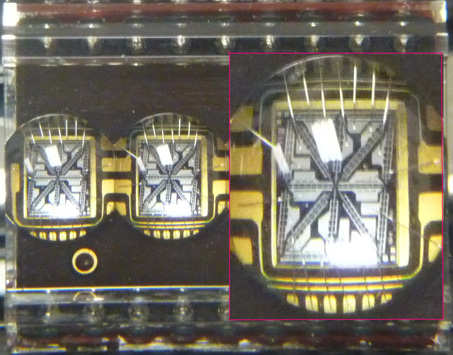
P1030412S2This is from the 1980s, it’s all red LED segments or dots.  I tried to find an angle where the ceiling light would not show, but because it’s a bubble lens, just about any angle had that white  reflection.  The specifications are available on the ‘net.  The box outlined in red is one of the characters blown up to twice the size.  More on this and a photo, but not as close up, in my previous blog.

default

2013-04-02 Salvaging Toroid Cores Part II

 Chocolate?

Paul has talked about using hot glue to hold the circuit to a ‘chocolate block’, but I’m not sure if that’s the same as the European style connectors we can get from Radio Shack.  I did manage to find dark colored versions of them in a Google search, but the only color I’ve ever seen is white.  I use them on various projects by cutting off a few of the twelve position version.

Dead CFL Lights

CFL lights usually have a small toroid core that can be removed and rewound with heavier wire.  The ones I’ve obtained make decent JT coils.

Also, the CFL usually has a choke that’s a round cylinder with two radial leads (coming out one end).  You can use this by winding a second winding on top of the shrink tube covering.  Just add some black electrical tape, glue or clear nail polish to hold it in place.  Even regular adhesive tape will hold the wires.

Mickey Mouse

There is another way of using two of these chokes side-by-side to make a coil.  The ones in my earlier blog are axial, the a single lead comes out of each end, but the radial chokes (leads both come out of the same end) should work similarly.  I have never seen any commercially made product use this method, and in my opinion it’s a Mickey Mouse way of doing it, but it works.

Don’t forget that you can get some cores from mouse cords, keyboard cords and keyboards.  Any cable that has a plastic bulge close to the connector has a potential core.  You may have to cut off the cable and plastic, but it’s usually a core that’s good for a JT – maybe bigger than you want but will handle larger wire.  I said ‘and keyboards’ because there may be one or two cores on the wiring inside of the keyboard, so you’ll have to open it up to find out.  These cores are in the 6 to 10 mm size range, an ideal size for a JT.  Just make sure you put the unwanted circuit board in the e-waste pile until you accumulate enough to take to the recycler.  Some waste disposal companies will do e-waste pickup at the curbside if you call them to schedule a pickup.


© RustyBolt.Info/wordpress
CyberChimps