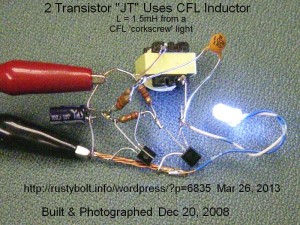
 I put this together during the Xmas holidays back in 2008. It may have been posted to my watsonseblog, I don’t remember. But here it is for the world to see again.
It’s the typical 2 transistor voltage boost circuit – often mistakenly called a Joule Thief – with a BC337-25 for the driver transistor. I used the choke or inductor from a defective CFL light bulb. The two transistor circuit allows the use of a coil with a single winding. The DC resistance of this choke is high which reduces the output and decreases the efficiency, but it puts out some light, as can be seen in the photo.
I see that the 100 pF “102” capacitor has a paralleled pair of 22k resistors (equal to 11k) in series. Recently I put a 10k or 25k trimpot in series and adjusted it and noticed that the LED gets brightest at some point of a very broad peak. Apparently this resistance makes the current pulse broader, and there’s a point where it’s at an optimum width. This resistance, the capacitor and the inductor influence the circuit parameters that determine the frequency of the circuit.