


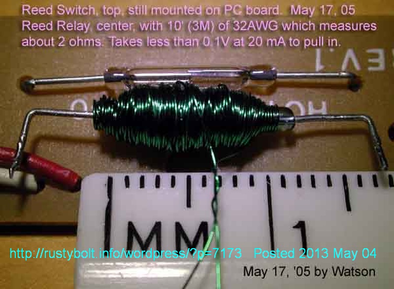
 I made this reed relay in May, 2005 and posted it to my late great watsonseblog. I think it hasn’t been posted here yet. It closes at less than a tenth of a volt, which is way too low voltage. This means I need many more turns of much finer wire. But it was difficult to wind the 32 AWG wire, and I wouldn’t want to wind even finer wire.

2013-04-23 Homemade Reed Relay Is Too Low Voltage


2013-04-21 Triple Transistor Low Voltage Joule Thief
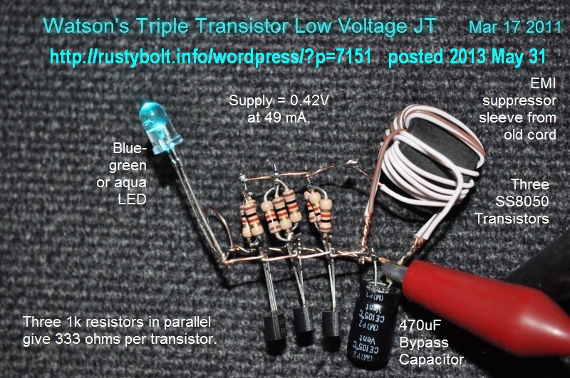 This Joule Thief uses three SS8050 high current transistors, each having a 333 ohm bias resistor (actually three 1k resistors in parallel). At less than a half volt, it gobbles battery current, 49 mA at 0.42 volts. That is a lot more than the typical JT, which drops to a very low current as the voltage drops below 1V. The JT will draw excessive current if the supply voltage rises above 3/4 volt. This circuit might do well on a single solar cell in broad daylight. It will work on two solar cells in series, which should give nearly a volt in broad daylight. But the solar cells should be matched to the circuit so that the current will not exceed the circuit’s maximum.
2013-04-20 Heavy Duty Joule Thief
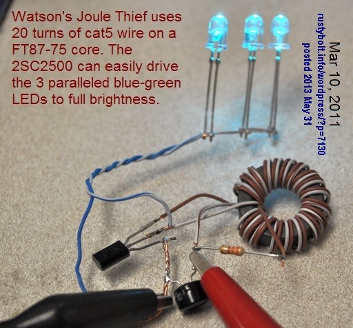 This JT uses a larger core that is typically found in low frequency applications such as EMI and RFI suppressors. This toroid has high permeability so it doesn’t take many turns to give a high inductance for a JT. The FT87-75 can be found at Surplus Sales for a dollar or so apiece.
The 2SC2500 transistor is a high gain, high current NPN, made for circuits such as a JT. The case is larger and it can handle more power, but the transistor doesn’t get warm.
2013-04-19 Dual Core Joule Thief
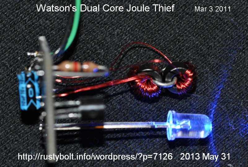 When the winding gets tough, double up the number of toroid cores, I say. This JT uses toroid cores that are less than 1/4 inch (6.4mm) outside diameter. The wire has to be fine to get several inches wound on a core. So I wound one core with the wire, and then coupled it to a second core by putting a single turn loop of heavy wire through both and soldering it. Then the second core could hold the remaining turns of wire. The cores are closely coupled electromagnetically, so they sort of act as a single core.
The cores don’t have to be small to be coupled together with a single turn. Two large cores could be coupled, as could two cores of different sizes. However, if they’re different sizes or different magnetic properties, that may affect the way they work in the Joule Thief. I’ve never seen any documents on this method, so I wouldn’t know what to expect if they were different. This might make a good topic for some major experimentation. Perhaps someone could use it as a topic for a thesis in college.
Back to experimenting…
2013-04-18 Hydraulic Ram a Mechanical Analog of Joule Thief
Paul suggested this Wikipedia article. I quote:
I remembered these, having seen one in action, and always wanted one. I think you might be interested. Perhaps that is why I am interested in JTs. There is more than a simple parallel.
When I was a kid, one of my dad’s customers died and his widow made my dad an offer that he couldn’t refuse: she would sell him all of her late husband’s tools and supplies – a whole shedful, for a very reasonable price. So my dad bought all of this plumbing tools and supplies and brought the stuff home and filled our shed to the rafters with the stuff. Being a curious kid, I started playing with this stuff, everything from pipe and fittings to the pipe threader and pipe wrenches of course. I became an amateur plumber. I also became fascinated with the things I could do with the pipe and fittings and a garden hose that supplied water. Soon I had built a lawn sprinkler and put enough pipe and fittings together to outfit a house.
My dad’s barber shop was a few doors down from a used book store. He used to take me over there and let me pick out some books, things like science books and books about dinosaurs and such. He perused the magazines and always managed to find a few Playboy magazines for his barber shop.
One book that fascinated me was a book on how things work. Things like steam engines (it was a very old book) and electrical generators and internal combustion engines and the pulleys in a block and tackle, and how the dam causes the reservoir to build up enough pressure in the penstocks to turn the turbine, which drove the generator, which powered a whole city, and on and on. One thing that I learned about was a hydraulic ram. Since I had this experience with plumbing stuff, I thought that it might be cool to build one, but I could never find the check valves and other special parts to make one.
Is a hydraulic ram the mechanical equivalent of a Joule Thief?
Many times I and others have used an analogy to show how an electronic device worked. The Wikipedia article at the end compares the Joule Thief to the hydraulic ram, and if you click on the talk tab, the discussion gets into greater detail on the comparison (but I haven’t read much of it yet). One thing I am certain of, the hydraulic ram puts out a more or less steady stream of water, because of the storage tank. The conventional Joule Thief does not have the electrical equivalent of a check valve and a storage tank. The JT would need to have a diode and capacitor added to the output between the transistor and the LED. The LED is a diode, but the voltage doesn’t reverse polarity and the LED gets intermittent pulses of current. I guess you could compare it to a hydraulic ram without a tank and just a nozzle which squirts out a stream each time the valve closes. These pulses would be roughly equivalent to the pulses of light from the LED.
2013-04-17 3V and Higher Joule Thief
The conventional Joule Thief uses a single cell at 1.5V for power. It also typically uses a coil that has both windings the same number of turns. This means that the voltage across the primary, which is also the voltage across the LED, is the same as the voltage across the feedback winding. Almost all LEDs have a forward voltage of 3.3 volts down to 1.8V for red, so a single cell will not light the LED. This is the purpose of the Joule Thief – to light the LED with a lower voltage.
We can put two or more LEDs in series on the Joule Thief, which will have a forward voltage of more than 3.3 volts: from 3.6 volts for two red LEDs up to 6.6 volts for two white or blue LEDs. But with two white or blue LEDs, the voltage across the primary winding will be at least 6.6 volts, and this is reflected back to the feedback winding, since it has the same number of turns. The typical transistor has an absolute maximum reverse voltage across the emitter to base junction of 5 to 6 volts, and the peak voltage from the feedback winding will exceed this. So what do we do? Reduce the number of turns of the feedback winding, so the voltage stay be able s below the maximum. If the feedback winding has half the turns of the primary winding, then the voltage will be half, and 6.6 volts on the primary will be 3.3 volts on the feedback winding.
Note: QS reminded me that the primary voltage has 1.5V or whatever the supply voltage is already added to it, so this voltage must be subtracted from the feedback voltage. With a 1.5V cell, the 3.3V LED should have 1.5V from the cell plus the rest of the voltage from the primary winding, which should be about 1.8V peak. But I’ve seen the voltage across the LED climb to 4.5 volts peak, so I would guess that the actual voltage the primary adds is about 3 volts.
This will allow us to put two LEDs in series on the primary. Since the LED forward voltage is higher, it will also allow us to use two cells in series for a 3V supply. Normally, with a single cell, the starting voltage would be 1.5V, and the ending voltage would be 0.6V, which is about 0.9 V total. With two cells in series, the starting voltage would be 3.0 V, and the ending voltage 0.6 V, for a total of 2.4 V, a much greater change overall. Each cell should be able to run down to 0.3 V, half the typical JT value.
One other benefit is that since the supply voltage is higher, the current can be lower for the same power to the LEDs. This also puts less demand on the transistor and the losses will be lower. More than two LEDs could be connected in series across the transistor, as long as the ratio of the coil windings is changed to keep the maximum voltage across the emitter to base junction below 5V, and the maximum voltage across the emitter to collector less than the transistor’s maximum rating, which might be 40V for a PN2222A or 2N4401, but could be as high as three hundred volts for a high voltage transistor such as the MPSA42. The coil windings might have a 5 or 10 to 1 ratio.
Another Circuit
Another way to boost a low voltage without using a specially wound coil is to use a two transistor circuit like the one in my previous blog. The coil is a choke or inductor with a single winding. A small amount of the current is fed back through a small capacitor to the first transistor to keep the oscillations going. But the voltage is no longer limited by the first transistor, it is limited by the second transistor’s maximum collector voltage and the load, which might be several LEDs in series. One important point I should make is that the demands on this inductor are greater with a greater ratio between the input voltage, which was 3 volts in our earlier example, to the output voltage, which might be 20 or 30 volts.
2013-04-16 Very Low Power Joule Thief
A question a Youtuber brought up made me think about going to the opposite extreme from the one I normally pursue: trying to get a Joule Thief to run at very low power. Normally I would try to maximize both the light output and efficiency.
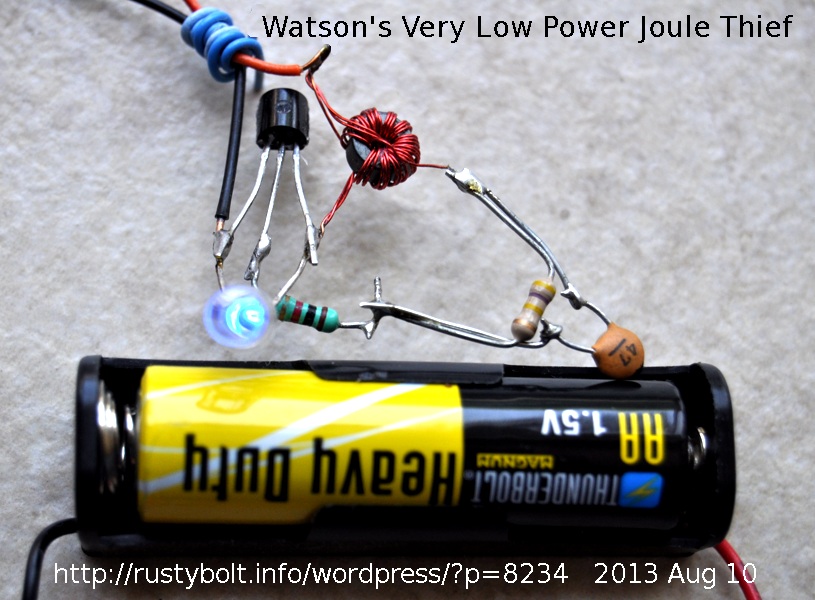 I started out with a run-of-the-mill Joule Thief having a coil, a BC337-25 transistor, a 1k resistor and a blue LED. The coil was a T231212T core only a quarter of an inch (6.4 mm) O.D., with four windings of 7 inch lengths of 30 AWG enameled wire wound quadrifilar, with three of the four windings connected in parallel for the primary winding. The blue LED lit up very brightly, and the supply current was the typical 60 or so milliamps. In order to reduce the LED brightness and the supply current, I chose to increase the 1k resistor. I added a 100k pot in series to allow me to adjust the brightness. As I adjusted this pot from 0 to 100k, the brightness dropped a lot, but the LED was still putting out quite a bit of light.
I decided I would try a higher resistance, so I put a 51k in series with the pot, and as I adjusted the pot to a resistance above 110k, the LED went dark. Well, I figured that the problem was being caused by the loss of drive from the feedback winding, which also had to go through this 110k or more resistor. I clipped a small capacitor across the resistors so that it was in parallel with the total 151k of the pot and 51k resistor, but it was still in series with the 1k resistor. The capacitor was a .0047 uF or 4.7 nF. The LED lit up again, but not brightly. So now that I had the LED working, I could again increase the total resistance, so I put a 470k in series with the 150k and put the capacitor across the 470k and 150k, but leaving the 1k resistor still in series. The LED still stayed lit, so I measured the supply current, and it was only 60 microamps, which was very low.
I removed the 4.7 nF capacitor and replaced it with a 470 pF, which was 1/10 the capacitance of the 4.7 nF. I couldn’t tell if the LED was brighter, so I put the 4.7 nF across the 470 pf, and the LED got slightly dimmer. Weird. This meant to me that there was some sensitivity to the size of the capacitor, so I removed both caps, and connected a variable capacitor that could be adjusted from 10 to 150 pF. When I adjusted this capacitor I found that there was a point where the LED lit up brightest. So I left the capacitor at that spot, and disconnected it and measured its capacitance, and found that it was 37 pF. But this peak was very broad, so I got a 47 pF capacitor from the spare parts box and soldered it in, and the LED lit up not very brightly, but it was clearly visible. I measured the supply current, and it was 310 microamps, or slightly less than a third of a milliamp. That is very low power: 1.5V times 0.00031 amp is about 0.000465 Watt, or 465 microwatts, not even a half milliwatt. Comparing that to the usual 120 milliwatts for the Joule Thief, it was about 250 times lower in power. Wow, I now had a very low power Joule Thief!
You might think why did I leave the 1k resistor in there. Well, I connected a jumper across the 1k, and I couldn’t see any change in brightness of the LED. So I figured that it didn’t make any difference. All these resistors added up to 620k, so I replaced them with a single 1 meg resistor. I measured the supply current, and it was 240 microamps. The frequency was 29 kHz.
When I put the 150k in parallel with the 1 Meg, the supply current jumped up to 1.7 milliamps and the LED got a lot brighter. I figure that with the 1 Meg resistor and a quarter milliamp battery current, a fresh alkaline AA cell running 24 hours a day should last for several months. With the 150k resistor, the battery should last for about two months. But this assumes that the battery current will remain the same during that time. We all know, from our Joule Thief experiments, that the battery current tapers off as the battery voltage drops, so the LED doesn’t go out, it just gets dimmer and dimmer. So in these cases, the LED could still remain lit for weeks more.
I left the blue LED pointing up toward the ceiling and the battery connected, and with the battery current at a quarter of a milliamp I can clearly see the spot of blue light on the ceiling when the lights are out. That’s not bad for a half a milliwatt of power.
Conclusion
Using the conventional Joule Thief with a resistor of a much higher value, and a small capacitor in parallel with it, the experimenter can control the battery current down to a fraction of a milliamp and still have a LED that is bright enough to see clearly. The battery lifetime will be greatly extended, and the LED can still put out enough light to be useful. By using a 1 meg pot in series with a 1k resistor to limit the maximum current, and the 47 pF capacitor across them, the experimenter can make a Joule Thief that is adjustable from very low light up to full brightness, and anywhere in between. The pot should be a logarithmic taper audio pot to give better control at the brightest end. And the left or lower resistance end of the pot should be connected to the coil winding.
This very low power technique could be applied to the twenty LED strings I recently blogged. The light output is much lower but the battery life could be extended to a month or more. Try this very low power Joule Thief out and see what happens; you might be pleased with the results.
Back to experimenting…
Update Apr 17 – In an email, Paul said, “I note you used quad winding but with such low currents surely that is not needed”. With such low currents, that might hold true for the low current in the transistor, which gets pushed to its limit at low voltage and high current. But with the core windings, which have the resistance of copper wire, the losses don’t change, percentage wise, as the current goes lower. If you have 100 milliamps or 100 microamps current, the DC resistance doesn’t change, and still wastes the same percent of power, even though the amount may be very small. Another point is that at higher frequencies, the Skin Effect takes effect. That’s why Litz wire is better than solid conductor wire. So having three conductors instead of a single conductor gives more surface area and the skin effect has more surface to give better conduction.
I took a look at the waveform with the o’scope, and saw that the waveform is a much narrower pulse than the typical JT. It is somewhat lower amplitude, but a good part of the lower light output is from the lower duty cycle (on time) of the pulse. When I put a 22k in parallel with the 1 Meg, the pulse amplitude gets higher, but the pulse gets a lot wider, and the transistor stays turned on longer. The circuit has been running on a ‘heavy duty’ (not alkaline) cell for several weeks, and the cell voltage is 1.435 volts. Looks like it will run at least a month more on this cell.
Let’s assume, for the reason of eliminating it as a factor, that the pulse height didn’t change when the 22k was put in parallel. What we then have is a change only of the duty cycle; the on time of the 1 Meg is much lower than the 22k’s on time. But remember that the only time there are losses in the transistor is when it is switched on. Now the coil has losses in the resistance when the transistor is turned on and charging the coil. When the transistor is turned off and the coil is transferring its energy to the LED, there is current flowing, so I assume there is also loss in the coil. But the current is much greater during the on time which leads to the conclusion that most of the loss occurs during the on time. My point is that due to the high current during the on time, there is a justifiable reason to minimize the DC resistance of the coil’s primary winding so the losses will be minimal.
Update May 12 – I connected the low power JT up to a 50 Farad supercapacitor. The base resistor is a 470k resistor in series with a 1k resistor. There’s a 47 pF capacitor across the 470k only. I connected a fresh AA cell across the 50F cap, charging it up to 1.56 volts. I connected it to the JT, and set it aside. After 8 hours, the capacitor voltage was 1.137 volts, and the LED was still glowing, a bit weaker but still very visible. At 12 hours, the cap voltage was down to 1.05V, and the LED is still going, not as bright as it was, but still fully visible. At the 20 hour point, the voltage has dropped to 0.890 volts, and the LED is still lit, slightly dimmer than earlier. At the 24 hour point, the voltage is now at 0.865 volts, and the LED is getting dimmer, but still plainly visible. Next morning, thirty hours later, the voltage has dropped to 0.809 volts, and the LED is getting dimmer. And finally at 44 hours, the voltage has dropped to 0.704 volts, and the LED has dimmed to where it looks like it’s ready to go out – there’s very little light, just a faint glow.
Note: One thing that could be added is a switch to bypass part of the resistance and increase the brightness when it gets dim. This could also be a variable resistor or potentiometer, but just two switch settings should suffice. The switch could be a SPDT center off switch so the on/off switch serves a dual purpose. The idea is to allow the user to ‘turn up’ the light when the capacitor has discharged.
A later blog about this is here.
2013-04-15 TIA Thanks In Advance: Has It Finally Died?
Years ago I started seeing TIA or Thanks in advance at the end of emails and messages, and the thought occurred to me about what these people were trying to say. I’ve never used it, simply because it seemed inappropriate to me. I’ve always used thank you or thanks, meaning that I’m showing my appreciation for anything and everything that the reader might do for me – it’s unconditional.
Some not very thoughtful person came up with this TIA, implying that his thank you is for the future, when and if you have done something for him. In other words now that he has thanked me in advance, I am obligated to do something for him. I thought that was rather shallow minded, and it reminded me of my dog when I was young. We taught her to roll over and rewarded her with a doggy treat. Then when we were eating at the table, she would sit there at our feet, waiting until we looked at her, and then she would roll over with the expectation of being fed a piece of meat. Like, if she could talk, she would say, “Now that I’ve rolled over, you owe me some food.”
Like I said, my thank yous are an unconditional blanket appreciation for anything the reader does for me, even if it’s only reading the message and nothing else. In the last few years, for some reason I have seldom seen anyone use the TIA. I say, good riddance.
2013-04-14 Fluorescent Joule Thief (Instructable)
One of my email correspondents and botmaker, Bill Sherman, had made some Joule Thiefs inside of a jar, but this Instructible uses diluted fluorescent ink from a Highlighter pen to diffuse the light into various colors. That’s quite a nice idea, and gives the light a very dispersed and colorful look.
What I would like to see is some fluid that has the same properties that the phosphor has inside of the white LEDs. I could put a bright blue LED inside of the fluid and it would glow, radiating whatever the color the fluid happened to be. My guess is that since it’s a fluid, it may not be stable and long lasting. In that case, the fluid might be changed to a clear liquid that hardens, such as casting resin. Just mix up the fluorescent stuff in it, and catalyze it, insert the LED and wait for it to harden. Maybe one could just use a Highlighter pen to stir the resin, and enough of the ink would dissolve into the resin to do the job. One concern would be that if you ever had to change the LED, it wouldn’t be easy! I suppose it could be drilled out and a new one inserted into the hole. But hey, it doesn’t cost that much to make a whole new casting.
Back to thinking up some more wild ideas…
2013-04-13 What Is Germanane?
A few years ago, there were news articles about the great potential of Graphene, a type of carbon or graphite. I would say graphene to someone and they would say, “do you mean graphite?” And I would say, no graphene – no one had heard of it yet. As this article says, graphene is being researched, but nothing commercial has resulted from it yet. Now the newest buzzword seems to be germanane, which in one respect is like graphene in that it is a single layer of atoms, of germanium. Quantsuff sent me a link to this article, with the subject “Germanium Makes a Comeback?” If it does, it will be in a completely different form than the original germanium transistors. (Here is an article, and another here.)
I’ve read about SiGe chips, which are being made commercially, so germanium is still around though in a much modified form. The chips have advantages over Silicon only chips for certain applications. So germanium is still being used for some specialized chips. But as with graphene, it may be many years before chips made of germanane come out of research and get into commercial production. Hopefully it will be sooner than later. It would be great if they would be able to sell us a smart phone that would fit into a wristwatch. I was about to say into our ear, but I think that having high power radio frequencies that close to our brain might be a serious health concern. I guess that for display purposes everyone would then have to wear a pair of special glasses, like the Google Glasses. It seems that all of the electronics could already be put into such a small device, but there still seems to be a problem with getting the device to be low enough power so that the batteries can also be small enough. Perhaps germanane will be an improvement in this respect. If not that, then perhaps it will allow the speed of the chips to be increased, to get more done with less power.
I hope that the gov’t keeps funding this basic research, so germanane gets scrutinized thoroughly. Things look bleak for this type of funding since it’s one area that seems to be a candidate for big funding cuts. I hope not. The next big breakthrough could be just around the corner.
