These schematics are from a RADAR Data Processing System used in the military in the early to mid 1960s. They show how the vacuum tube and transistor versions were designed. I’m blogging them to show that the blocking oscillator circuit, similar to the Joule Thief, has been around for a very long time.
2013-07-11 Watson’s Pet LED Garden Rock
I came across this in a “99 cent” discount store, for a dollar. The UPC code is 39277 75124. They also had the standard garden lights for $2, with the plastic stake to poke into the ground. I bought one of those and opened it up, and found that they had gone cheap, and used a AAA cell, instead of the earlier ones with an AA cell.
With this garden rock, I decided that for a dollar, I could get a solar photovoltaic cell, a white LED with a reflector and a battery, so it was worth the investment. I figured that it would have a AAA cell inside just like the $2 garden lights. The thought never occurred to me that the case was so small that the AAA cell might not fit inside (but I did managed to squeeze one in diagonally).
Everything was underneath the solar cell, which was hot glued into the case. I pried it off gently with a small screwdriver so as not to chip or break the solar cell. The circuit board isn’t worth anything to me; the black blob on it covers all the silicon devices, and the 470 uH choke is a poor choice for a Joule Thief due to its high resistance and high losses.
But the rechargeable cell is really a big disappointment. I was expecting something bigger than a little green button cell. I don’t see how these could run for more than an hour or so after the sun sets. My guess is that the circuit was designed for lower current drain on the button cell, and much lower LED light output, of course – that’s the only way they can make the button cell last for more than an hour or so. If so, then replacing the button cell with a larger AAA cell will not increase the light output, and there’s no way to modify the circuit for more light output. The label says it’s a 1.2V AG13 rechargeable cell, and it’s not replaceable. It says 40 MaH, and charge is 4 mA for 14 hours.
The circuit shuts off the LED when there’s light on t he solar cell, and it’s quite sensitive. Even the light inside the house is enough to shut it off. And this light is too low to recharge the battery. This leads me to conclude that if the experimenter wants to experiment, the circuit needs to be replaced.
Should I go back and buy a few more? I really like the reflector, which costs two dollars if I order them from online. That’s really expensive considering the companies that make these rocks are paying only a few cents for them. So I think it’s worth buying them just for the reflector, if I can get it out without damaging it. The solar cell is worth a few dollars. The switch can be reused. But the button cell, well, if I could get three of them and put them in series, and charge all three with a 4V solar cell, then they might be able to run a single LED. I think what might be a solution is to put a new board inside, and use a bigger battery. The case is really ugly, so I may salvage the solar cell and LED/reflector and use some other container, like an Altoids tin. I’ll have to do some measurements on the solar cell to find out how much current it can put out in sunlight. I may need two or more solar cells to charge a discharged AA cell during the daytime.
2013-07-09 FBI Says Fingerprints Are Infallible, No 2 Are Alike
I recently watched the Frontline episode on PBS that dealt with criminal prosecutions based on fingerprints, bite marks and other evidence. The FBI claimed that the fingerprint system is infallible and that no two fingerprints are the same. The FBI arrested a guy in the U.S. for a crime that happened in Europe, on the basis that his fingerprints matched a single partial print found on the crime scene. It later turned out that the fingerprint was that of a terrorist, not the guy in the U.S., which proved that the FBI’s claim that fingerprints are infallible is not true.
This brought to mind my neighbor, Esther Glaser. Esther was born at about Thanksgiving in 1912, so she was about 91 when this picture was taken. She passed away after her 99th birthday. She told me about her experience with the FBI a long time ago, probably during WW 2, when her husband’s business did contract work with the U.S. Government. They had to be fingerprinted, and later the FBI agents came to ask her why she had smudged her fingerprints. She showed them her fingers. There were no fingerprints! Yes, I looked at her fingers, and saw that she did not have any fingerprints – her fingers were as smooth as a baby’s butt. I said, “Esther, you would have made a great burglar.” She smiled and said “I know!”
The FBI has known about her case for many decades. So if their fingerprint system is infallible and that no two fingerprints are the same, how do they explain her case? How many other people in the world or the U.S. have no fingerprints? I have personally witnessed at least one myself – Esther – so I would expect that there are others, no matter how rare.
2013-07-08 LED V Boost – A Decade Ago
In the early days of my LED flashlight experimentation in August of 2003 I was experimenting with LED V boost circuits and wrote up the following note. I don’t remember what the circuit was – might have been a Joule Thief.
LED V Boost, Low V
Input V = 1.503V
Input I = 16.3 mA
Total input power: 24.5 mW
Assumed LED V = 3.3 V
Meas. LED current = 4.4 mA
LED power = 14.52 mW
Efficiency = 59.3%Changed output transistor from BC337 to a BC639. It made no difference in current consumption or output current.
Apparently I was trying different transistors to see how to maximize the current and efficiency. It’s obvious that I didn’t have enough power to the LED. At that time I was using coils with a lot of turns and high resistance, probably on a toroid with low mu. That’s probably the reason why the circuit was not putting out much power.
2013-07-06 How To Make a Trimpot An Odd Value
Often an experimenter needs a variable resistance and adds a trimpot to the circuit. For instance I want a resistor that can be varied between 220 and 330 ohms. The easiest solution would be a 220 ohm resistor and a 100 ohm trimpot in series. But I don’t have a 100 ohm trimpot, which is a very uncommon value. I have a 1000 ohm trimpot, so can I use that instead?
Let’s see how we can do that. The circuit doesn’t say that the resistor or trimpot has to be a single part. You can put two resistors in parallel and get 220 or 330 ohms. Let’s try this: leave the 220 ohm resistor to be the minimum, and replace the 100 ohm trimpot (that would have been in series) with two resistors that can be varied between 0 and 100 ohms.
I take a guess at the resistor that I want to go in parallel with the 1000 ohm pot. I guess 150 ohms. So I take my calculator and enter 150 and press the 1/X key. Then I press + and enter 1000 and pres the 1/X key. Then I press the = key and 1/X key and I get 130.43 ohms.
That’s a bit too high, so I take another guess, and enter 120 into the calculator and press the 1/X key and + key. Then I enter 1000 and press 1/X key, press the = key and then 1/X key. I get 107.14 ohms. That’s just about right for the maximum.
As I vary the 1000 ohm trimpot, which is in parallel with the 120 ohm resistor, it is going to give a resistance that is between 0 and 107 ohms. The linearity of the pot will be affected. The resistance will change less at the high resistance end of the trimpot, and change more at the low end of the trimpot. But we can now use a 1000 ohm trimpot to do the job of a 100 ohm trimpot.
Any two resistors in parallel can be found by adding their conductances. The conductance is equal to 1 divided by the resistance. So before adding the resistance you entered, you press the 1/X key to change it to conductance. The unit of conductance is the Siemens, which at one time was called the Mho. This procedure also works for capacitors in series. But if you have two resistors or capacitors of the same value, just divide that value by two. Two 1000 ohm resistors in parallel equal 500 ohms, etc.
Back to experimenting…
2013-07-05 Phase Shift Oscillator Using a Regular Transistor

First off, I must state that the PSO is not the best solution for an audio oscillator. It uses only a single transistor, but it has a limitation that makes it put out a poor quality sine wave. As typical of the PSO, the sine wave becomes distorted because the loop gain is greater than unity and the amplitude of the sine wave grows until the transistor goes into either saturation or cutoff, and the sine wave gets clipped. If you want a clean, stable sine wave, then use a Wien Bridge Oscillator.
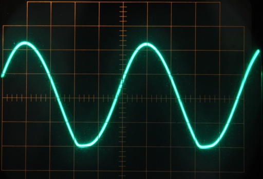
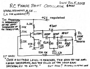
The previous JFET PSO was so finicky about adjustment that I was very concerned that it would not work if the temperature changed. I found a PSO schematic that said that the gain of the amplifier decreases when a suitable level is reached. But how? I thought. One way to find out if this was the case was to build the circuit. I tack soldered the parts together and it oscillated when powered up. I checked the scope and found that the sine wave was not quite what I had expected but it was better than many other PSO sine waves.
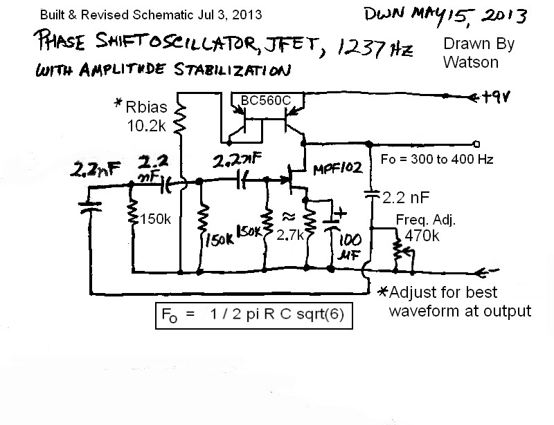
So I proceeded to make some changes to the circuit to get the sine wave to look better (see the o’scope photo). I used a pot to vary the value of the two 22k resistors that set the base bias. The changes are shown in the schematic. I chose a very high gain transistor because its higher input impedance is less of a load on the CR network, but a 2N3904 or similar should work. It just happened to be that the frequency was just a bit over 1 kHz, 1024 Hz or so. I added the 560 pF capacitor to lower the frequency down to about 1008 Hz, but since the three 10 nF capacitors are 5 percent tolerance, the difference between sets may be enough to need more or less added capacitance. It would probably be better to use a 5.1k for one of the resistors, and put a 1k pot in series so the frequency can be adjusted higher or lower.
It showed the RL as 100k or more. The reason is that the load changes the gain of the transistor and can change the amplitude of the sine wave or even stop it from oscillating. The best solution to this would be to add another transistor to buffer the sine wave and prevent load changes from changing the oscillation. The original circuit had only R3A, the 3.3k resistor. I added the 10k R3B to reduce the feedback somewhat so it wouldn’t cause so much distortion in the sine wave. It also lowered the frequency slightly; the reason is the transistor’s base, the two base bias resistors and R3 A and B are the actual resistive part of the third CR section. This should be closer to the 5.6k of the two other resistors, but it isn’t, it’s more than R3 A and B, which is 13.3k.
I found the formula for calculating the frequency at several websites. They say it’s 1 / 2 / Pi / square root of 6 / R / C or .065 divided by R, divided by C. In both cases, R and C must be in their fundamental units, such as 5600 for R, which is 5.6k, or .00000001 for C which is 0.01 microfarad. If your calculator has exponent, then you can use E-6 for microfarads or E-12 for picofarads.
I have calculated the values for the schematic shown, and it is assumed that the third CR section, which is actually the resistance of R3A, R3B, and the input of the transistor, But the input depends on the gain of the transistor, so it may change with different transistors. The 12k and two 22k resistors are about equal to 9.4k, plus the R3 A and B, for a total of about 22k. That is much more than 5.6k, so the formula gives a different answer than the 1008 Hz that’s the actual frequency – it’s more than ten percent higher. The conclusion that I make is that for a regular transistor, the formula is not accurate enough due to the unknown resistance of the transistor and its bias resistors. It should be okay for a JFET which has a very high input impedance. But that’s not the case for a single BJT. I could use two transistors in a compound connection similar to a Darlingoton, which would raise the input impedance a hundred times or more. Then the base bias resistors would be almost all of the input impedance.
Measurements
The supply voltage was 6.0V. I measured the voltage across the 470 ohm emitter resistor at 0.65V. That would be about 1.38 mA. I measured the total supply current at 1.5 mA, so that seems about right given the base bias resistors take some small amount of current. The actual frequency was 1008 Hz; according to the formula it should be 1160 Hz. The scope shows a slight clipping at the bottom of the sine wave. I adjusted the supply voltage and found a point where the distortion was minimal, but this point was at an odd voltage. To get that point to 6V, the bias resistors would have to be changed. It would oscillate at 5V or 9V if the bias was changed.
Update Jul 11 – I removed the 10k in series with the 3.3k, so that the value of R in that last CR section is more equal to the other 5.6k resistors. The frequency moved up to 1091 Hz. The 12k and 44k resistors in parallel are equal to 9.43k. In addition the 3.3k resistor in series makes 12.73 k. When the transistor’s resistance is included, I’d guesstimate the combined resistors is somewhere close to 10k. That’s almost twice the 5.6k resistors.
The sine wave had a bit more distortion in it. I decided that I could add resistance to the 22 uF emitter bypass capacitor to reduce the gain of the transistor and lower the distortion. I unsoldered one end of the 22 uF and put a 100 ohm trimpot as a variable resistance in series with the lead. I set the trimpot at minimum and powered up the circuit. The sine wave looked like it did before, so I turned the trimpot up. The sine wave got less distorted but then the oscillations died. The trimpot setting was very touchy; just a small change from the low distortion setting to no oscillation. I adjusted it as best as I could for low distortion, shut it down and measured the trimpot resistance, and it was 36 ohms.
Which brings me back to the point where I was when I did the JFET PSO. With the gain lowered to get the minimal distortion, the gain is at the point where it equals the loss of 29 in the CR network. This wouldn’t be a problem, except as the temperature changes, the transistor’s gain changes, dropping as the temperature gets colder. If this circuit was exposed to cold temperatures, I’m sure that it would stop oscillating. What is needed is a feedback loop that adjusts the gain, depending on how high the output voltage is. As the gain changes, the feedback loop compensates for it and holds the output voltage at a point below where it starts to distort. I’m writing a blog about changing a trimpot in a circuit so that it is not as sensitive.
BOGUS Circuits
I found this web page with a photo with two PSO circuits, one a transistor and the other with an opamp. The transistor does not have an emitter resistor with a bypass capacitor. This means if the supply voltage changes just slightly, the operating point will change and cause the sine wave to become distorted or stop altogether. The circuit has four CR sections, but the resistors are 1k, which is much lower than the 3.3k collector resistor, and that loads it down too much. The values of this circuit were poorly chosen.
The opamp circuit is bogus, and will not work. The two 1k resistors of the CR sections should be connected to ground. They are shown connected to the feedback line. That’s a major mistake. If the website admins knew something about electronics, they would have caught this, but they don’t, apparently. Instead, some unsuspecting experimenter will try to build the circuit and become frustrated when they cannot get it to work. Long ago I complained to someone about a major mistake. The reply I got was “You got what you paid for.” They were implying that they paid nothing, so they should not expect to get something for nothing. I think that was a very bad attitude. It also showed that many of these websites are not concerned about the interests of the viewer, all they are concerned about is getting people to view their advertising. I think that is also a bad attitude. And think about this: the website is making money from the hits or views they get from viewers, so the viewer in turn should reasonably expect to get something for their view.
Back to experimenting…
2013-07-04 Dollhausen’s Joule Thiefs
I came across this web page with some very interesting Joule Thief designs and I thought I should pass it on to others. If I can find the place, I’ll also put it in my home page.
When I started building my LED voltage boost flashlights back in the 2001 to 2003 years, we were afraid we might get caught in an elevator with no light during one of the rolling blackouts that the power companies were telling us might happen. I had a number of small flashlights, mainly the Mini Maglites, but I wanted something that used a LED that would not burn out if it was used for a long time. I started building flashlights into Altoids tins, but they were too big for the pocket. That was when I started investigating smaller flashlights using a single AA cell and some kind of circuit to make the 1.5V drive the higher voltage LEDs. That was when I developed the circuit that I put into the Velamints tins. Here is the inside. Another one is shown here. It’s on the top of the second pile from the left.
The pile shows several of the others I built during the Energy Crisis in California. At that time you could not buy a LED flashlight at the store; then when the first ones came out, they were fifty or more dollars, so almost no one could afford them. About the only way to get one was to make your own. So I made my own. What I’m alluding to is that my Joule Thiefs were born of necessity and practical needs. So the art factor really didn’t come to my mind. Nowadays, a LED flashlight is available at every store for a few dollars, and I think the art part of a Joule Thief gives it a more noble reason for its existence.
2013-07-03 EuroConn Joule Thief “SIM”
This, I believe, is the first Joule Thief I’ve built using a European style connector, I call them EuroConns, but Paul calls them chocolate blocks (I’ve never seen one chocolate color, though). I’ve built other things with them. If you’ve ever watched the Youtube videos of Xee2 AKA Xee2vids, you’ll know how handy these can be for quickly putting together circuits. These are available in 8 and 12 position versions from Radio Scrap. I call it a “SIM” because it’s a Single Inline Module.
It was a bit of a stretch to get the leads of the PN2222A transistor to fit into the three holes, but I finally got it. It should have a socket or extension wires, but soldering extension wires onto the leads kind of defeats the purpose of the strip, which is to get away from soldering.
The JT uses a PN2222A, a 1k resistor, a high Mu toroid core with two separate windings, look like 9 turns each, and a Seoul Semi 1 watt warm white ‘star’ LED. The connections are pretty much self-explanatory. The white wire from the black lead of the LED to the black negative lead (far left) can be replaced with a 1 ohm resistor to monitor the LED current. I haven’t made any measurements, probably because I plan in disassembling it after I’ve blogged it. It’s JAAJT (just another average Joule Thief).
Back to experimenting…
2013-07-02 Phase Shift Oscillator, JFET Continued
I blogged a schematic on May 15, but it took me until now to build the schematic. I tack soldered the PSO together with the components shown, except I did not use the two diodes and two 10k resistors.
First off, according to this article, to get it to oscillate, the overall voltage gain of the JFET has to be at least 29 to make up for the loss in the three CR sections.
The turkey circuit would not oscillate, and I have spent more than an hour trying to get it to oscillate by adjusting the values for the source bias resistor and the drain load resistor. I checked the values for the three resistors in the three CR sections and found each to be 150k.
For the source resistor I’ve used a few values from the 1k shown up to 2.7k, all with the same 100 uF bypass capacitor (however I did temporarily add another 100 uF to see if it would help). I started out with a 3.0k drain load resistor and put a 10k pot in series with the drain load resistor and found that the hum that I got on the scope when I touched my finger to the gate would decrease as I increased the pot. This indicated that the gain was reduced as the resistance increased. The maximum hum amplitude was when the total resistance was about 4.3k.
So far, the circuit refused to oscillate. I decided to add a fourth CR stage to the other three. Now each stage has to add 45 degrees phase shift, and this reduces the losses in the CR sections to less than 29, which should help make it easier to oscillate. But it still stubbornly refused to oscillate. But I noticed that the hum seems to be a bit higher amplitude, and the bumps in the hum seem to be bigger, which seems to indicate that the circuit is a bit closer to oscillating. But close isn’t good enough, it has to be oscillating.
I gave up on it for later, when I have a bit more patience.
Idea – I thought about replacing the drain load resistor with the collector of a PNP transistor. The emitter would be connected through a 330 ohm resistor to the positive, and the base would have two resistors to bias the transistor with enough current to serve as the load resistor. The collector has a very high impedance, much better as a load than a conventional resistor. I’ll have to think about what the circuit schematic will look like.
I came up with the following. I used two BC560C NPN transistors. I connected the collector and base of one together and to the base of the other BC560C. I connected both emitters together; I soldered these to the positive 9V. I soldered the remaining collector to the drain of the JFET, making these into the drain load resistance. I soldered the bases to the wiper of a 100k pot, and the end of the pot to negative.
The pot allowed me to adjust the amount of current through the collector-base to emitter junction. This then forward biased the other transistor with a fixed collector current. With the PSO powered up, I adjusted the pot and the scope showed it oscillating when I finely adjusted the pot over a very narrow range. The resistance change was very small; too low and the oscillations died; too high and the oscillations again quickly died. I adjusted the pot for the best looking sine wave, which, by the way, looked very good with little distortion – that’s unusual for a PSO. I disconnected the pot and measured it, and got 10200 ohms. I replaced it with a 10k and 220 ohm resistors in series. I powered it up, but no oscillation. I adjusted the supply voltage a bit and the sine wave appeared, and I measured the supply voltage at 8.6 VDC. It is a very touchy circuit.
The frequency was 405 Hz. As it is now, the PSO has four CR sections. The frequency is lower than what I expected; I was expecting closer to 1000 Hz, according to the formula in the schematic. I could understand if the additional fourth section changed the frequency somewhat, but I don’t think it would be that much. I went to the link at the bottom of the Wikipedia article about PSOs. The value it came up with was 196 Hz, less than half the frequency I measured.
I can adjust the frequency a bit with the 470k pot on the fourth CR section. Increasing the pot changed the frequency to below 300 Hz with very little change in amplitude or distortion. But if I go above 420 Hz, the amplitude rapidly drops and then it stops oscillating. I’m happy to see that the frequency can be varied that much with only a single pot. If all four resistors in the CR sections could be varied, the frequency range could be the whole audio range.
I have already said that the supply voltage is critical, and any change would cause it to stop oscillating. So the circuit would need a well regulated supply, and for this circuit 9V would be about optimum. This would also help stabilize it against frequency changes. But one thing I’m concerned about is changes with temperature. Frequency changes can be minimized by using good quality capacitors and resistors in the CD network. But what will happen to the transistors? When I changed the bias slightly, it stopped. Will temperature change it enough to stop oscillating, or will the waveform become distorted?
And I need to change the CR section values to get the frequency I had planned. I will have to search for a calculator that can do four CR sections. These questions will have to wait for another time when I can heat or cool the circuit to see what happens. One thing I can say for this circuit: when it is adjusted correctly it has the best sine wave I’ve ever seen for a PSO. Another thing I can say for this circuit is that the JFET is so low gain that the likelihood is low that it will work when the temperature changes; I’ very concerned about that. I updated the schematic and posted it above. 🙂
Update Jul 6 – I built another PSO with a regular BJT (bipolar junction transistor). This one worked from the start, and compared to PSOs I’ve built previously, the sine wave looks much better. The blog is here.
2013-07-01 Peltier Flashlight
QS sent me a link to a design that supposedly uses four Peltier tiles to generate enough light to be used as a flashlight. Apparently there are no further details.
There are some points to ponder in what the link said:
It used the word ‘objective’, which means it’s something that they hope to achieve, not the actual results.
It said four tiles in the palm of the hand. The body’s extremities are the lowest temperature parts of the body, and have no heat generating muscles. That’s a really bad choice for a temperature difference.
The sentence beginning with “My design” quotes figures that have no basis in fact. Putting it simply, there was no design.
So this all adds up to hot air, cheap talk and Vaporware. Once the design is revealed, then we shall see.
They would do better by designing a mechanism that fits the arm and pivots at the elbow. This mechanism would then transform arm motion into electric power. It should be a lot easier to generate milliwatts. This intermittent electric generation would then be stored in a supercapacitor and then used to light the LED.
I guess I will have to eat crow. Here she is, with the demo flashlight, and the technical details.


