


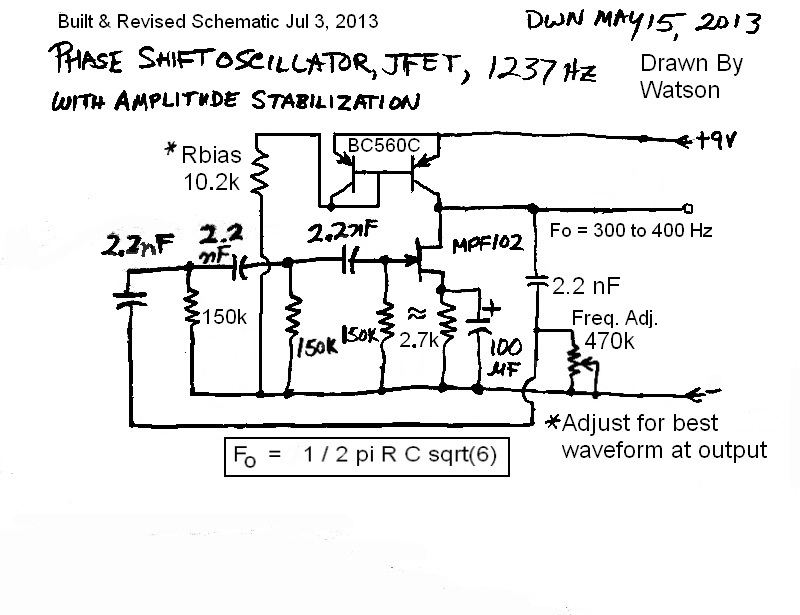
 I blogged a schematic on May 15, but it took me until now to build the schematic. I tack soldered the PSO together with the components shown, except I did not use the two diodes and two 10k resistors.
First off, according to this article, to get it to oscillate, the overall voltage gain of the JFET has to be at least 29 to make up for the loss in the three CR sections.
The turkey circuit would not oscillate, and I have spent more than an hour trying to get it to oscillate by adjusting the values for the source bias resistor and the drain load resistor. I checked the values for the three resistors in the three CR sections and found each to be 150k.
For the source resistor I’ve used a few values from the 1k shown up to 2.7k, all with the same 100 uF bypass capacitor (however I did temporarily add another 100 uF to see if it would help). I started out with a 3.0k drain load resistor and put a 10k pot in series with the drain load resistor and found that the hum that I got on the scope when I touched my finger to the gate would decrease as I increased the pot. This indicated that the gain was reduced as the resistance increased. The maximum hum amplitude was when the total resistance was about 4.3k.
So far, the circuit refused to oscillate. I decided to add a fourth CR stage to the other three. Now each stage has to add 45 degrees phase shift, and this reduces the losses in the CR sections to less than 29, which should help make it easier to oscillate. But it still stubbornly refused to oscillate. But I noticed that the hum seems to be a bit higher amplitude, and the bumps in the hum seem to be bigger, which seems to indicate that the circuit is a bit closer to oscillating. But close isn’t good enough, it has to be oscillating.
I gave up on it for later, when I have a bit more patience.
Idea – I thought about replacing the drain load resistor with the collector of a PNP transistor. The emitter would be connected through a 330 ohm resistor to the positive, and the base would have two resistors to bias the transistor with enough current to serve as the load resistor. The collector has a very high impedance, much better as a load than a conventional resistor. I’ll have to think about what the circuit schematic will look like.
I came up with the following. I used two BC560C NPN transistors. I connected the collector and base of one together and to the base of the other BC560C. I connected both emitters together; I soldered these to the positive 9V. I soldered the remaining collector to the drain of the JFET, making these into the drain load resistance. I soldered the bases to the wiper of a 100k pot, and the end of the pot to negative.
The pot allowed me to adjust the amount of current through the collector-base to emitter junction. This then forward biased the other transistor with a fixed collector current. With the PSO powered up, I adjusted the pot and the scope showed it oscillating when I finely adjusted the pot over a very narrow range. The resistance change was very small; too low and the oscillations died; too high and the oscillations again quickly died. I adjusted the pot for the best looking sine wave, which, by the way, looked very good with little distortion – that’s unusual for a PSO. I disconnected the pot and measured it, and got 10200 ohms. I replaced it with a 10k and 220 ohm resistors in series. I powered it up, but no oscillation. I adjusted the supply voltage a bit and the sine wave appeared, and I measured the supply voltage at 8.6 VDC. It is a very touchy circuit.
The frequency was 405 Hz. As it is now, the PSO has four CR sections. The frequency is lower than what I expected; I was expecting closer to 1000 Hz, according to the formula in the schematic. I could understand if the additional fourth section changed the frequency somewhat, but I don’t think it would be that much. I went to the link at the bottom of the Wikipedia article about PSOs. The value it came up with was 196 Hz, less than half the frequency I measured.
I can adjust the frequency a bit with the 470k pot on the fourth CR section. Increasing the pot changed the frequency to below 300 Hz with very little change in amplitude or distortion. But if I go above 420 Hz, the amplitude rapidly drops and then it stops oscillating. I’m happy to see that the frequency can be varied that much with only a single pot. If all four resistors in the CR sections could be varied, the frequency range could be the whole audio range.
I have already said that the supply voltage is critical, and any change would cause it to stop oscillating. So the circuit would need a well regulated supply, and for this circuit 9V would be about optimum. This would also help stabilize it against frequency changes. But one thing I’m concerned about is changes with temperature. Frequency changes can be minimized by using good quality capacitors and resistors in the CD network. But what will happen to the transistors? When I changed the bias slightly, it stopped. Will temperature change it enough to stop oscillating, or will the waveform become distorted?
And I need to change the CR section values to get the frequency I had planned. I will have to search for a calculator that can do four CR sections. These questions will have to wait for another time when I can heat or cool the circuit to see what happens. One thing I can say for this circuit: when it is adjusted correctly it has the best sine wave I’ve ever seen for a PSO. Another thing I can say for this circuit is that the JFET is so low gain that the likelihood is low that it will work when the temperature changes; I’ very concerned about that. I updated the schematic and posted it above. 🙂
Update Jul 6 – I built another PSO with a regular BJT (bipolar junction transistor). This one worked from the start, and compared to PSOs I’ve built previously, the sine wave looks much better. The blog is here.


