default

2013-11-10 Holder for Camera (Cell Phone)

IMG_20131111_184528S1-CameraHolderA few weeks ago I made this camera holder for my Samsung Galaxy S4 out of a piece of 1 inch aluminum angle bar.  The part in the photo that is attached onto the tripod with the C clamp is the holder. I’m using a C clamp to hold it on because I have not yet drilled a hole in the holder and added a 1/4 inch nut to fasten it to the tripod foot.

I have a Body Glove rubber protective case on the S4, and it slides right into the holder snugly and will not come out unless I give it a good pull.  I have been using it for a few weeks and it comes in so handy that I had to blog it.  When I want to take a hands free snapshot or a movie, it’s the only way to go.  It’s just like a third hand.  The original reason I just had to make it was because I wanted to do time lapse movies, and holding a cell phone absolutely still for even just a few minutes is nearly impossible and my arm gets tired and I have to give up.  Time lapse videos are great, they can show a car trip of a half hour in just a minute or less.  But the camera has to be held still during the shoot.  And that’s too much for a person to do with his hands.

Also, the holder allows the camera to be mounted on a person or bicycle, like a GoPro video camera.  With this holder mounted to a hat or helmet, I could get some fantastic videos.  I can now mount the holder onto a remote control copter and fly it overhead.  There seems to be no end to the places to go and things to do when the camera can be held and positioned optimally.

Someone should sell these, but make them out of tough plastic so they’ll last for awhile.  Also add some adjustments so that one holder could fit many different sized cell phones.  Someone could make a lot of money with a successful design.

default

2013-11-08 Flash! Banana Erupts In Flames!

I was in for a very big surprise today when I pulled a banana out of the fridge and put it into the microwave for fifteen seconds to take the chill out of it.  I pressed 15 and the start button and watched.  About the 14th or 15th second this large fireball erupted from the end of the banana and went BZZZZZZT!  It scared the hell out of me!  I pulled the door open to stop the microwave oven, and pulled the smoldering banana out of the oven.  I looked at the stem end, and found out what had happened.  It got really hot really fast, and literally caught on fire, but then the steam inside of the stem spurted out and blew a jet of smoke out of the end.  The microwaves turned the smoke into an arcing ball of flame!  The end if the banana was still smoldering embers as I looked at it.

The lesson I learned is if I want to prevent this from happening again, I should cut the stem off of the end of the banana before I put it in the Microwave oven.  But then, just maybe, I might try to do it again. (sly smile!)

default

2013-11-05 Blog Uses Joule Thief As Battery Charger

I got a Google Alert that pointed to a facebook page for a Joule Thief.  In that page I found a link to this UK blog about using a Joule Thief as a battery charger (click on the link to the .PDF schematic).

The Joule Thief circuit is a typical example of a conventional JT.  Instead of a 1k resistor, the author uses a 50k pot.  He should also include a 1k resistor in series with the pot, so if he turns it to minimum it will prevent the transistor’s base current from becoming excessive and damaging the transistor.

The author winds a separate winding on the toroid core and connects this to the AC inputs of a full wave bridge rectifier (FWB).  Then the rectified DC goes directly to a LED light (and also through a 10 ohm resistor).  One characteristic of a full wave bridge is that it has two diodes in series with the current, so each time it rectifies there is 0.6 to 1 volt drop for each diode, or 1.2 to 2 volts drop total.  The power wasted in the FWB is more than the power that is going to charge the battery.  Combine this with the approximately 50 percent losses in the Joule Thief itself, and the charging battery gets less than 25 percent of the power that is drawn from the “run” battery.  This is very wasteful.

Most people don’t remember that the LED is a light emitting DIODE.  This means that it will also rectify the AC into DC, so actually the FWB is not needed at all.  The only thing that one has to do is try connecting the winding to the LED first one way, then the other way (swap the wire ends).  The pulses from the winding are not symmetrical and will light the LEDs brighter one way than the other.  Leave the leads connected whichever way the LEDs are the brightest.

The idea of using the Joule Thief or a similar circuit called a Bedini SSG came from those experimenter who were trying to ‘harvest energy’ and make a circuit that has a a COP (coefficient of performance) of greater than unity.  More can be read about this at overunity.com.

default

2013-11-04 Audio Preamp, Two Transistor

IMG_20140101_142155This was in a schematic from the 1960s, the days of silicon transistors, before low noise op amps.  The 2SC369 is old and very likely to be no longer available.  The replacement transistors could be any low noise small signal, such as the BC550C or 2N5088.  The supply voltage shown is 34 VDC, but this can be reduced by reducing the 10k resistor to 1k for example, and increasing the 100 uF.  For best low noise performance, the resistors, especially the 100k and 270k, should be low noise metal film type.

External to the circuit, there was a rotary switch on the front panel which switched the input between phono, tuner, etc. and also the corresponding N.F.B. to the output.  Following the circuit there were volume and tone controls and then the power amplifier.

I digitized this and posted it Jan 1, 2014.  It was probably drawn in the 1980s.

default

2013-11-02 W_eb 2011-08-07 Dual LED Odd Colors

A 2011-08-07 watsonseblog post from the Way Back Machine: (the second resistor is a 1 ohm resistor in series with the LED for measuring the LED current.)

2011-08-07

2011 Aug 07 Dual LED Odd Colors


When a white LED is connected to a power supply or 6V battery, in series with the required current limiting resistor, it will light up and the forward voltage across the LED will be about 3 volts. Then if I connect a red LED in parallel with the white LED, the red LED will light up and the white LED will be dark. The reason for this is that the red LED has a forward voltage of about 2 volts, and that is much less than the white LED, so all of the current will go through the red LED.

Yet in the picture, I show a red LED and white LED connected in parallel, and both are lit! How could this be? Am I defying the laws of physics? It certainly seems so.

First off, let me say that this is just a conventional Joule Thief with the coil on the left, the transistor which is hidden behind the yellow clamp jaws, and the resistors. The red LED leads are inserted between the white LED leads and are just touching them. The red and white LEDs really are both lit, I didn’t make any mods to the picture. Anyone can do the same thing by putting a red LED in parallel with a white LED in a Joule Thief. The current through the white LED alone was measured at 18 milliamps (9 millivolts across a 1/2 ohm resistor). With the red LED in parallel, the current went up to 40 milliamps.

The white LED dimmed a lot, which is understandable since the red LED has lower forward voltage. The reason the white LED did not go out is that during the transistor’s off time, the peak current from the coil into the red LED is very high and the voltage across the internal resistance of the red LED rises to more than 3 volts, which is enough to allow some of the current from the coil to go through the white LED. Thus both LEDs light up, however the white LED is getting a fraction of the total current and the red LED is hogging most of the current.

But the seemingly impossible still happens: the red and white LEDs both light up. The secret is in the high current pulses from the JT’s coil.

default

2013-11-01 TP3051J Telephone CODEC IC

P1030628S3Here’s a pic of a TP3051J telephone interface chip (CODEC and Filter).  Yes, a picture of the actual chip inside of the IC, after I popped the top off of it.  I have a lot of them so I figured that checking one out to see what was in it would be fun. The pic isn’t very good because it was taken through a magnifying glass which is not color corrected.

I’ve searched but can’t find much about it except the National datasheet.  All I know is that a lot of chip brokers will sell it if you submit a request for a quote.  I won’t do that, never ever again.  I got onto one email list of a BCBFH (search for BOFH) and they refused to take my email address off their mailing list.  I even called them but as is usual with crooked companies, they told me the sender of the email was not in, and to leave a message, which most likely was never even written down, or else tossed in the trash can.  I tried to report them to their ISP, but it didn’t help.  I finally put a filter in to trash any emails from them.  This is in clear violation of the U.S. CAN SPAM Act laws.  If anyone knows of a circuit that uses this chip, I would appreciate an email to my yahoo.com email address, acmefixer or leave a comment.

default

2013-10-31 DC to DC Converter For Receiver

I noticed my fellow group members in the Yahoo Group RegenRX are often using a 9V battery to power their projects.  This blog is a way to save them a lot of money if they use a lot of 9V batteries.  First, the 9V pro’s and con’s, then the DC-DC converter pro’s and con’s.

For a source of 9V power, there is nothing cleaner  than a 9V battery.  It makes no RF interference (RFI), no electromagnetic interference (EMI), no hum and very little audio noise.  The batteries are easy to obtain and found at most stores.

The 9V alkaline batteries are ridiculously expensive (however the 9V ‘heavy duty’ batteries are a dollar at the dollar store).  I went past a display at the Target store and saw that two name brand alkaline 9Vs were eight dollars.  For that much, I can buy 16 to forty AA cells, or sometimes more at Fry’s or online.

The DC-DC converter circuit is simple and easy to build.  It uses parts that can be bought mostly at Radio Shack.  It can use a single AA cell if the load is low power, but for 9V power at over 20 milliamps it would be better to use two AAs in series for 3V, and the cells will last longer.

For RF receivers, the converter has one drawback that can be a problem if the builder doesn’t do due diligence: it can cause RF interference.  I have used a converter on an AM / FM pocket radio and found that the FM works okay but the AM band has a lot of interference.  I changed to 470 uF electrolytics for the filter capacitors and that reduced the noise a lot, but what it takes is some RF chokes and the ferrite sleeves that are found on keyboard USB cables and VGA cables.  A few well placed EMI sleeves on the cords and power leads should help a lot.  Remember that if you’re doing moon-bounce or deep space reception this may not be suitable.  But even if you decide that it can’t be used in your project, it’s capable of powering any other of your 9V toys, etc or projects, such as a crystal checker, transistor tester,  etc.

My DC-DC converters are not like the cheaper circuits you might see.  These are just a voltage boost circuit commonly known as a Joule Thief that uses one transistor and a coil to boost the 1.5V up to 3.2V to light a LED.  Except the LED has been replaced by a Zener diode, often 5.1V, that just wastes all of the power as heat while it acts as a shunt regulator.  The load taps off the Zener’s current and uses what it needs.  But the converter draws a steady load from the battery at its maximum current, and there is no change as the load varies.  Instead, my converter feeds back the output voltage to the converter, and when there is low or no load, the converter shuts down and reduces its drain on the 1.5V cell, so that the converter only supplies the load’s demands and the battery life is extended.

Here is a link to the DC-DC converter I built for my cheapo DMM.  It’s designed for only 8 or so mA maximum so that the battery will last a long time.  L I N K

Here is another link to a DC-DC converter that uses two transistors for the converter.  The second schematic uses two transistors that switch in a square wave instead of a single transistor that sharply cuts off and makes a steep waveform with a lot of harmonics.  This should reduce the amount of RF and electromagnetic interference.  Also the ratio of the windings on the transformer determines the output voltage.  The windings have just a dozen or so turns so they are not difficult to wind.     L I N K

I have some schematics out there from my old watsonseblog that are accessible but I can’t changes or corrections or delete them.  Some of the ones for DC-DC converters are in these links.  L I N K


default

2013-10-30 Mechanical Joule Thief

What would you say if I told you that I could make a Joule Thief without a transistor or other electronic parts, just a single mechanical part? Would you believe me?

I have seem this method used many times in old radios and old equipment made before transistors were born. It’s not magic! You may have even experienced it before, accidently.

I knew a guy who liked to play jokes on (former) friends. He had a small device that fit in his palm, and held a small battery. When he shook hands with you, it would give you a mild, harmlessness shock, and your reaction would be immediate! Yow!

Well instead of a palm shocker, we will use a small, low voltage DC relay. Preferably it’s for a voltage less than 5 volts DC, but if not available, then use a 5 volt relay. The contacts should close at less than 5 volts, perhaps 4 or even less volts.

We connect the C or armature terminal of this relay to one of the coil terminals. The other coil terminal is connected to the negative end of two AA cells in series. Two white or blue LEDs are connected in series, and the cathode lead with the flat spot is connected to the battery negative. note that the LEDs do not light because they require 6 volts, but the battery is only 3 volts. The other lead of the LED is connected to the coil and C terminal. The positive of the battery is connected to the NC terminal of the relay.

When that positive lead is connected to the NC or normally closed contact, the current goes to the C terminal and to the coil. This energizes the coil, which disconnects the NC terminal. With no more current flowing, the magnetic field in the coil collapses, and the voltage rises higher and higher, until it gets to 6 volts, where the series LEDs start to conduct. This causes the LEDs to light, and the coil discharges its stored energy into the LEDs. After this, the C and NC contacts close and the process starts over again.

We have just made a mechanical Joule Thief! We also have made a buzzer, depending on how loud the relay is. I should warn that this may put out so much energy to the LEDs that they might get too hot and burn out.

By adjusting the wire size and turns on the relay coil, it can be made to operate on just about any voltage. If the voltage is very low, a winding with additional turns may have to be added to step up the voltage to the LED or LEDs.

default

2013-10-29 Bright Lights, Big Campus

IMG_20131029_211319SOne thing I’m glad to see is that many of the problematic parking lot lights have been replaced. These are the ones with the big, pinkish yellow light in them that has what I call the ten off, ten on syndrome. Once the light has spent a half hour heating up, it stays lit for roughly 10 to 15 minutes, then goes off for about the same time until it cools and comes back on again. Someone wants to go to their car at night and it’s totally dark. They report the lamp as broken, and the maintenance guy goes out to check it. Well, he turns on the lights and this one works just fine for maybe 30 minutes until it gets hot, but by that time the guy has lost patience and wrote off the complaint as no problem found and leaves to fix something else.

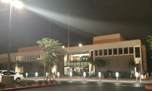
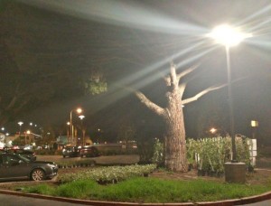
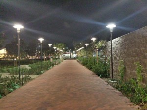
After the perimeter construction on campus was finished and the lighting was installed, I was leaving from work before dark and had not seen the new LED parking lot lights at night.  Tonight I stayed until after dark and took a few pictures of the LED lights in the parking lot (they’re BRIGHT!) and the decorative lighting in the walkways, etc.  You may have to click on them more than once to enlarge them to full size.

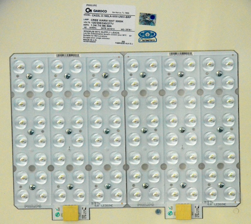
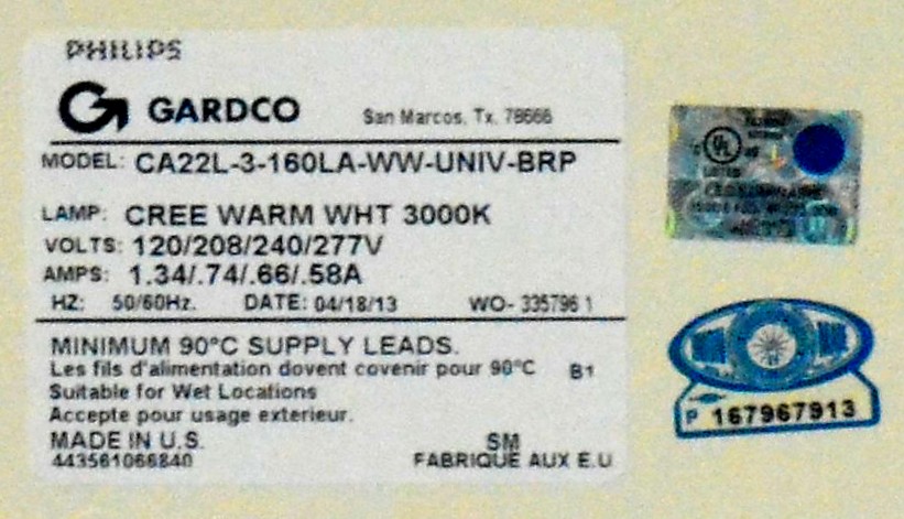
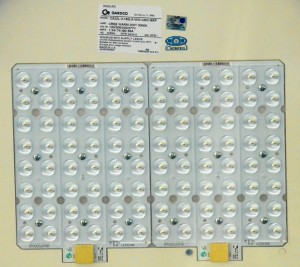
The last images are of the LED light itself.  The pics were taken fifteen feet below with a telephoto lens so they aren’t all that clear, but that’s as close as I could get.  There are eight rows of 12 LEDs per row, for 96 LEDs total.  As the label says, they’re Cree.  I find that odd, because Philips is (or was) a part owner of LumiLEDs and I thought they made their own LEDs.  But then if you need 96 per light, that’s a whole lotta LEDs and you may need to obtain a lot of them from any source, including the competition.   I looked up some light similar to this and saw they may cost anywhere from roughly $500 to $1600 (USD).  Some of those were not LEDs, so I’m guessing that even though the cost of LEDs have come down, the LED lights are probably on the high end of those prices.  At night they don’t look like warm white to me; they look like bright white.  But they are so bright that you can’t look directly at them, just like the sun.

IMG_20131029_210847S

I find these LED lights to be one of the few improvements that were made by the remodeling construction.  Not only was there 9 months of inconvenience with parking lots shut down, and construction dust and debris which is still ongoing, but the results afterward were worse in my opinion.  Many ‘improvements’ turned out to be detrimental to the campus in my opinion.

One example is signs that are on the cinder block columns that are located  at the exit to each parking lot.  Before, the signs were on a slender metal post which you could see around when you were looking for cross traffic on the road.  Now the sign on the cinder block column blocks the view of the road, and you have to pull out further into the road to see around them, making the exit more unsafe.

IMG_20131029_210545S
But I think the absolutely stupidest thing they ever did was to reduce and remove the cinder block wall around the perimeter of the campus.  Originally the wall was  about four feet tall, so most people would have to walk around it to get to the bus stop or cross the street.  Now in some places such as the bus stop the fence is about knee high and not difficult to step over for most people.  But when the bus gets ready to leave, you see these late people running to catch it.  Someone in a hurry is going to try to jump over the wall and fall and seriously injure themselves and our college will get blamed for making the wall unsafe.  In effect, it’s just more of an obstruction than it is a fence or barrier.

DSC_2505S1And then in some places they removed the wall and replaced it with shrubs which look like hedge plants.  This is going to get out of hand because it’s a lot more work than a wall to keep it watered, trimmed and maintained.  And this low wall or no wall will allow the middle school students walking down the street easier access to passing through our campus. with more negative results.  A few of these immature kids have become a graffiti and vandalism problem but now it’s going to get worse.   We install security cameras all over our campus, but really, what good does that do?  Once the tagger or vandal is on the campus and does his damage, the security camera may take a clear picture of him and even get a license plate on a vehicle, which will probably get reported to the police.  It’s doubtful that anyone will get caught and punished.  And you still have the graffiti that has to be cleaned up or covered up.  It’s a losing situation – it’s better to keep them out of the campus to begin with.

DSC_2505S2I will say that the LED lights are a huge lighting improvement, and will save money on electricity too.  But I drive around town and see the stop signals with red and green LEDs that have one or more rows of dead LEDs.  Or they flicker on and off like some kind of alien space ship.  They were fine for a few years after they were installed.  Then I guess the city decided that the maintenance had dropped so they could lay off most of the maintenance guys.  Now, a few years later, there are no longer enough maintenance guys to keep up with the LED light problems.  Will these LED parking lights suffer a similar fate?  These are up on a pole fifteen or more feet above the ground, so you can’t change one by standing on a chair, like a ceiling light.

For those astronomers out there, these lights will help cut down light pollution.  The LEDs are pointing down so that none of the light shines up where it gets wasted and ends up just causing a grey haze across the city at night.  However the flat top makes an excellent pigeon’s roost – or any other bird, for that matter.  It will probably end up getting a ‘porcupine quill’ or ‘spike strip’ plate on the  top to (hopefully) make the birds go away.  I saw some eaves with those strips and the flying rats (pigeons) just landed on them and dealt with them as best as they could.  I think chicken wire would have done a better job.

The electricians told me that the supply voltage to the parking lights is 277 volts, and the label says this LED light uses 0.58 amps at that voltage.  That comes to 160.66 watts.  I don’t know anything regarding how these LED lights are ballasted, but I assume that they use a SMPS (Switch Mode Power Supply).  This is much like the power supply in a computer, and wastes very little power during operation  – I’m guesstimating less than ten percent.  If these are 1 watt LEDs, then the total power input should be 96 watts plus 9.6 watts in the PS, totaling 105.6 watts.  Perhaps the 160 watts is the maximum value, and the light typically uses somewhere around 106 watts.

It looks like there are two arrays of 48 LEDs each. I would have to guess as to how the LEDs are connected.  Possibly all in series.  That would add up to 3.2V times 48 LEDs or 153.6V.  Two panels in series add up to 307.2 volts.  277 volts AC rectified and filtered becomes 385V DC, which would be enough to power two panels in series.  Then if the PS was a SMPS, it would be just as easy to have it put out 153.6 or whatever volts, and have that voltage current limited.
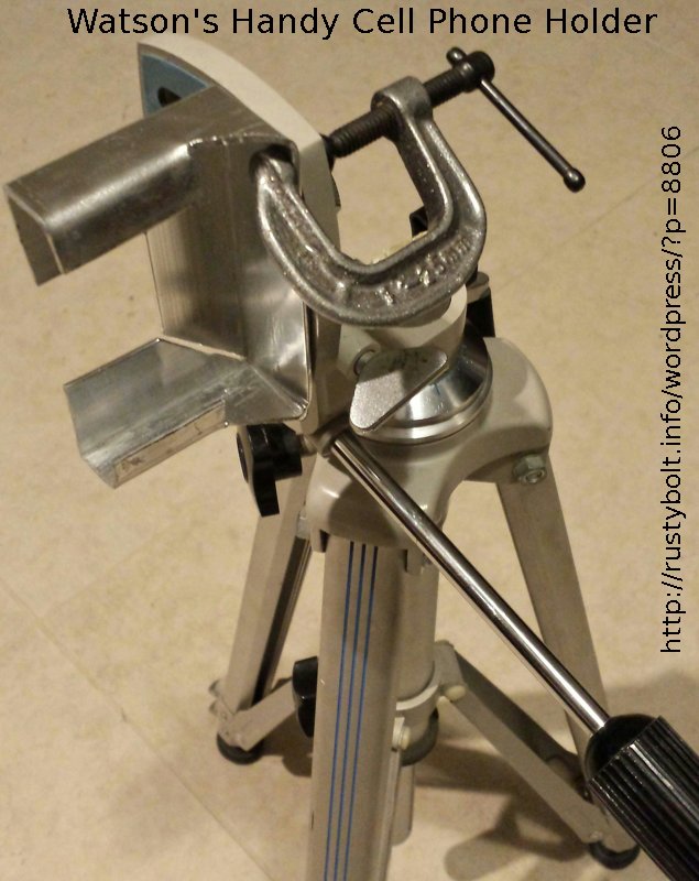
default

2013-10-27 Low Power Joule Thief With Photocell

IMG_20131027_161106S3One Joule Thief I have not built (at least not in the same JT) is the low power JT with the CdS photocell.  Almost all of my JTs with daylight shutoff used a LED as a light sensing diode, and then most were flashers.  I have a bunch of CdS photocells but I haven’t really tried to use them for shutoff because they are linear and will cause the circuit to shut off gradually, instead of abruptly.  They work better if they are used with a circuit that gives abrupt shutoff, such as a comparator or Schmitt trigger.  This time I just connected the photocell across the base and emitter, and it works okay, with some dimming, but it shuts off completely.  It is very sensitive; it doesn’t take much light to shut it off.

The rest of the circuit is a conventional Joule Thief with a 68k resistor in place of the usual 1k resistor.  This reduces the base current to the point where the battery drain at 1.5V is less than 10 mA.  That’s about 1/8 of the usual JT current.  For the coil I used a Fair-Rite 2643002402 core with about 9 turns which gave an inductance of about 100 uH.  The transistor was a SS9014D (D means it’s the highest gain range, a very high gain 400 to 1000). It’s a low noise audio transistor, with a max current of only 100 mA.  I reckoned that it would work okay since the battery current was less than 1/10 of that.  The 2N3904 doesn’t have high enough gain, only 300 or so; with the much higher gain SS9014D, the resistor can be much higher and when the CdS shorts the base during daylight, the battery current will be only 22 microamps, which is so low that the battery will last a very long time when it’s shut off. Remember that if the circuit is left indoors where there are lights on much of the time, it will shut down during the lit periods.

I assembled it on a 9/16 by 1-1/16 inch piece of thin birch plywood.  I probably would have had it together and working in less than an hour, if I hadn’t goofed and crossed the wires of one winding.  After I got that straightened out, it probably took me another ten or so minutes.  The only thing it needs is a spot of silicone or hot glue to hold the toroid firmly in place.  A coating of acrylic spray would be better to seal the wood to prevent it from absorbing moisture.  This is not critical since the impedances are only moderate; the 68k resistor is the highest.  But if it’s outdoors, it would be best to waterproof the circuit.

I had trouble getting a photo of it with the LED lit.  When the light was high enough to get a good shot, the LED would shut off.  And when the LED was lit, it was too dark for the camera, so I decided it would be shown without light.  I can say that the circuit meets my expectations, and if I want to make it less sensitive, I can enclose the photocell in something dark to cut down  the light and reduce the sensitivity.  The LED current is not all that much but it’s visible and can light up a small area.  I haven’t tried it at night but it may make a good night light.  At 8 or 9 milliamps, the AA cell will not last all that long, maybe a few weeks or a month.  I also have another idea that might work.

Well it’s now dark, and I measured the frequency while lit.  It measured 284 kHz, which is much higher than I had expected.  That’s 4 or 5 times higher than the typical JT, and indicates to me that the coil needs more turns.  There is enough room for 12 or maybe more turns, and if the feedback (purple) winding is changed to a finer wire, it could hold even more turns.  Perhaps the reason why it’s running so fast is the high value of the resistor.  With the base current severely limited, the transistor doesn’t get switched on and off fully, and it’s running more in the linear region, instead of saturating or cutting off.  This reduces the efficiency, but then it’s using very little power and the light output is adequate.  A small capacitor across the resistor might help to slow it down, but I haven’t got the inclination to try it since it’s working okay now.

The next day I put the LPJT near a small night light and I found that it’s sensitive enough to shut off when the dim light from the nightlight hits the photocell.  Now if I want it on, I just place a small object in front of the photocell and it comes on.  I used a pop bottle cap and  put the photocell inside so it’s surrounded by most of the cap.  Even like this, when the room light is on it still goes out.  Same for daylight.  I bought the night light in Feb of ’07 and less than a year later the cheap white LED in it had dimmed to the point where it was useless.  So I removed  the white LED and put in a yellow one, and it’s been running bright for more than 8 years.

One other thing it can do.  As long as the night light is on, the LPJT will stay off.  Then when a power failure occurs, the night light goes off, the LPJT comes on and acts as an emergency light.  The problem is that it’s okay for a dim night light, but for an emergency light it needs to be much brighter.  I think if I could get a regular power JT to shut off with a photocell and draw only a few dozen microamps, the cell would last long enough for it to work okay after a year or so.  But the normal 1k resistor would drain the cell in only a month or so.  It will probably need another transistor to reduce the photocell current down to the point where the cell will last a year or more.

© RustyBolt.Info/wordpress
CyberChimps