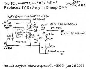
 I’ve been trying to get a stable 5 milliamps of current from this circuit, which is a Supercharged Joule Thief with the LED replaced with a rectifier, filter capacitor and zener shunt regulator. I’m getting about 9V with no load, but when I put a 2.2k load resistor on I get 8.5V which is drawing about 3.8 milliamps. I think 4 or 5 mA would be enough to run the DMM. The total current through the ZD1 is about 7 milliamps no load, so if the voltage drop doesn’t cause the DMM to complain, then this circuit might be able to fulfill its job of replacing the 9V battery. One other thing: it should have a bypass capacitor across the battery – 220 uF or more.
The circuit is not efficient overall because the output is shunt regulated. The Zener diodes just waste the excess that isn’t being used. But the inverter “Joule Thief” part of the circuit is efficient because it’s a Supercharged Joule Thief, This keeps the total current drawn from the battery down to 75 milliamps. If it was a conventional JT, the current would be over 100 mA. Since the DMM is used only intermittently, I figure that the single AA cell should last more than a dozen hours, which is weeks even in my extreme case of using the DMM every day. I could have used two AA rechargeable cells, which would be about 2.5V, and just keep trickle charging them when they’re not in use, I should experiment with another one that is optimized for 2.5V.
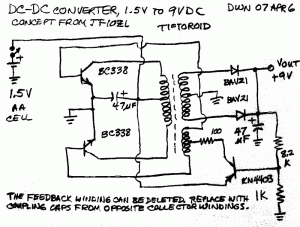
 I built a circuit in April, 2007 which used two transistors to drive the output. This lightened the current load for each transistor. The two push-pull transistors balanced the DC in the core and the center tapped output winding had two diodes for full wave rectification. I don’t remember whether or not the feedback regulated the output well or not. The blog I wrote about it went away along with that information when watsonseblog was removed.
I think there could be a few improvements. There should he a bypass capacitor from the center tap of the feedback (bottom) winding to ground. The 47 uF capacitor could be larger, 220 uF or more. The BC338 should be changed to BC337-25 to give a bit more balance to the two transistors. The 8.2k and 1k resistors should be higher, maybe 22k and 2.7k, to minimize wasted power. It might be a good idea to change the 2.7k to a 2.2k and 1k pot to allow adjustment of the output voltage.
Try this one .It is very efficient and works in my multimeter for quite some time . To increase efficiency one does not have to use 9v output for converter , 8-8.2V maybe a little lower will do just fine .
http://postimage.org/image/win4nxea9/