Posted to FB group 2017 June 8, then a copy here.
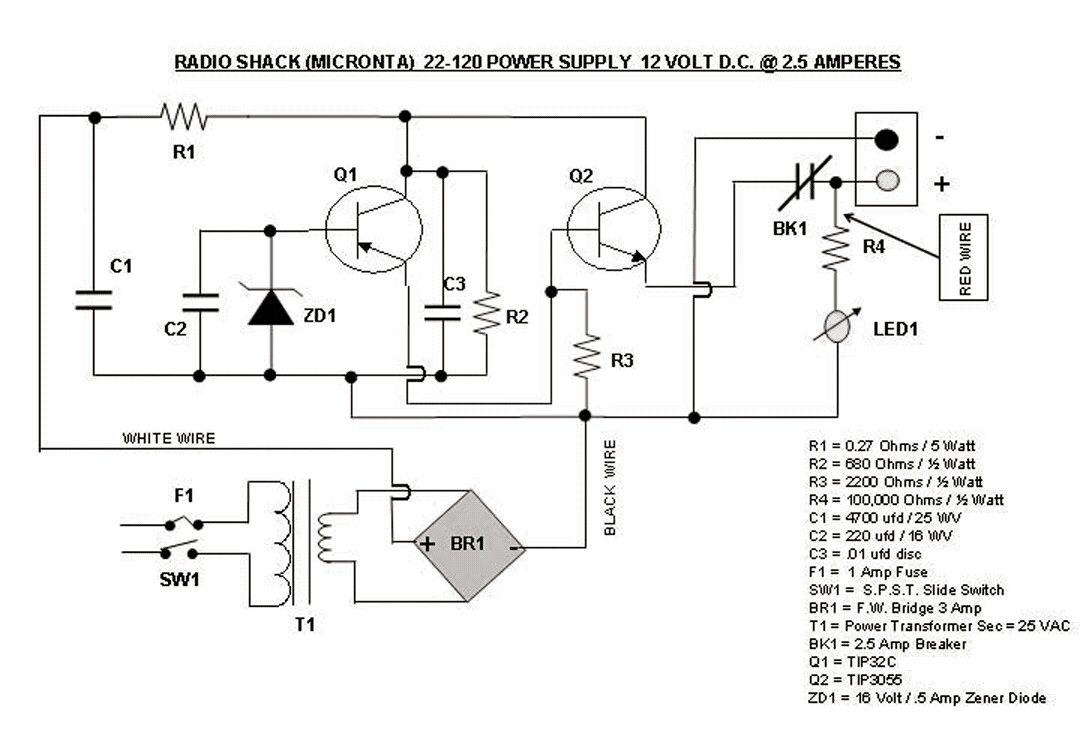
I found this Radio Shack power supply on Bama.edebris.com. Looks like someone drew it up. I found a few boo-boos, one being the LED having a 100k current limiting resistor. It’s not going to be bright.
I wonder if BK1 thermal breaker is capable of interrupting the current before the transistor(s) burn out. BK1 also causes a voltage drop so it contributes to poor regulation.
The drawing is somewhat confusing. R2 and C3 should be to the left of Q1. etc…
I also noticed that it says the T1 secondary is 25 volts. That means Q2 will have to dissipate an excessive amount of power in order to supply 2.5 amps. It also means C1 will have a lot more than its rated 25VDC, and will probably self destruct.
It looks to me like the Q1 PNP is bass ackwards, so I don’t think this schematic is ready for prime time.
