default

2011-12-29 Joule Thief Toroid Turns, Inductance

My watsonseblog dated 2011 Apr 12


2012 Apr 12 JT Toroid Turns, Inductance

I have some answers to the questions I read here.

What are the inductance ranges that work in the Joule Thief? What are the limits to the choice of turns?

What is the maximum number of turns and the minimum number of turns needed to get the Joule Thief to function?

Let’s start with the frequency, since that sets limits on the inductance and turns. For the lower limit, the frequency can be as low as a hundred or so Hertz, which is where flicker starts to become noticeable to the human eye. For the upper limit, anything below about 450 kHz should be okay as long as it doesn’t interfere with anything. The frequency could go higher, but the efficiency starts to drop and the RF interference could cause stations in the AM band to have interference.

To reach the upper frequency limit, the inductance could be as low as 10 microhenrys. This could be just one or a few turns for a high permeability (high mu or high μ) core, or a few tens of turns for a low permeability core or air core.  In other words, the inductance of the coil depends on the number of turns, which is dependent on the type of core material, the size of the core, all of which determine the permeability.

You might think that I should also include the size of the wire. But I’ve wound many coils with a bifilar (two wires in parallel) winding using different size wires such as 24 AWG and 30 AWG. When I measure the windings, their inductances are identical, even though the wires are very different sizes.

It’s possible to get a JT to light the LED with an air core coil of just a few turns, but the frequency might be several megahertz, and the stray capacitances of the circuit may cause a loss of efficiency. A common transistor such as the 2N4401 or PN2222 can oscillate as high as a hundred or more Megahertz. But there really is no point in going this high.

To reach the lower limit, it would take a hundred millihenrys or more, but with this high an inductance, the coil would become very large. The hundreds of turns needed would be very high DC resistance if the wire is thin, so heavier wire would be needed, and the coil would have to be physically larger. The coil might be as big as a golf ball (1-3/8″ or 35mm) or even much bigger depending on the core used. This would be too big, considering the circuit itself would fit on a small coin. Remember that a JT needs about a quarter amp peak current at 1.5 volts, and that is the same as a 6 ohm resistor on a AA cell. The coil must have a DC resistance that is much lower than this for a reasonably bright LED.

I hope this answers the questions. The Joule Thief is tolerant of a very wide range of coil inductance and turns, as long as the DC resistance or losses do not cause the LED to dim. And the overall size of the circuit will put a limit on the coil size, number of turns and inductance. This holds true for silicon small signal transistors.  Some transistors such as silicon power transistors and germanium transistors have much lower maximum frequency, which could be as low as a few hundred kilohertz or even less.  This limit could greatly reduce the maximum JT frequency and hence the minimum coil inductance.  I’ve found that germanium power transistors can’t go above a few kilohertz. The coil has to be high inductance, several tens of millihenrys, and physically large with heavy wire.

Back to experimenting…

default

2011-12-28 Another Blinking Joule Thief

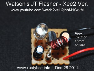
On Youtube, this guy named Xee2 or Xee2vids posts short videos of schematics, projects and circuits.  There is no motion, just slides, and no narration, no voice in his videos.  There is no way to comment to tell him if I’ve found a mistake.  But so far, most of his vids are very good with very few errors.  And most of the stuff is original and innovative.  One project caught my eye, a blinking Joule Thief.  The video gets to 35 seconds then freezes and won’t go any further, so I don’t know what the rest of it is about.  But I got the schematic and now I’ve built on to see how it works.

It’s a simple circuit, with all the parts of a conventional JT and adds a 10uF capacitor to get the circuit to flash.  I built it on a small perfboard but I’ve been having difficulties with it.  I put a 68k resistor instead of the 100k resistor called for in the schematic.  When I finished and powered it up, I got irregular flashes at about 2 per second.  But I couldn’t find the irregularity in the flash rate.  The schematic in his vid does not show a bypass capacitor across the 1.5V battery, so I installed a 10uF bypass capacitor.  While I was doing that I removed the 68k and put in a 120k which I figure should be closer to 1 a second.  When I finished and fired it up, nothing.  Voltages look normal and I didn’t change anything since the first time it flashed.  I’m puzzled why it’s not working.  Maybe the heat from unsoldering then soldering it back has damaged something.

Try It Again  I decided that it wasn’t worth troubleshooting the problem and built a second one, same as the first.  I’ll go over a few things.  These changes apply to both.   I changed from the MPSA06 to a PN2222A, which is not that different.  The original resistor was 100k, I changed to 120k, mainly because the flash rate was too high.  Even with 120k the flash rate is still fast, about 2 per second.  A better choice might be 180k or more. The capacitor was 10 uF, just like the original.

The Coil  The original used a “1 inch core from Electronic Goldmine, 5 for $1.00”, which has been sold out for some time, and will no longer be available, since they sell mostly surplus and it’s extremely doubtful they will ever be able to find them surplus again.  I still have some of these, so I wound 20 turns of telephone wire onto one core and measured the L and got 4.52 millihenrys.  But this core is too large for a low power Joule Thief.  Instead, I used a tiny 1/4 inch core from surplussales.com, which was about the same price.   It is the (ICH) T231212T, available for $.25 apiece.  As stated in the ad, they are high permeability, 5000 or more, so it doesn’t take many turns of wire to make a reasonable amount of L (inductance).  I used 7 inches each of 28 and 30 AWG enameled wire, wound bifilar onto the core.  The inductance was about 480 microhenrys, which is just fine for a Joule Thief.  I used a yellow LED,  mainly because a flashing white LED is totally boring – white LEDs are made for illumination – and I have a dozen Blue Blinky circuits madly flashing so I really don’t need another blue one.

The second one went together quicker than the first, mainly because I had the original to use as an example.  The perfboard was only 6 holes by 6 holes, where the hole spacing was 0.1 inch.  Everything fit nicely.

Test It Out  I connected it to the power supply and it flashed, about ten flashes every 7 seconds.  Still too fast.  But what was disappointing was the light output.  I could barely see the yellow flashes on the palm of my hand in a fully lit room.  The light output is so dim I can look directly into the LED chip and clearly see it flashing.  At this low current, the prediction he made about the AA cell should last for 8 years is very likely true.

But with the 120k and 10 uF, the flash rate was more than twice a second.  I removed the 10 uF and put in a 33 uF, and it now flashed considerably slower, but still flashed at 1.4 flashes per second.  The capacitor needs to be at least 47 uF to get down to close to 1 flash a second.  In order to increase the light output. the capacitor must be much larger – he suggests 10k and 100 uF, but I think 100 uF is still too low.  This brings up an important point.  This resistor is the only source of base bias current for the transistor.  The normal JT uses 1k, but here we have 100k, so it stands to reason that the base bias current is much less than a normal JT.  This looks to me like the main reason the LED is so dim.  The solution to more base current is a lower value resistor (the reason why he suggested using a 10k in the video).  But the more base current, the faster the capacitor charges.  So we have to increase the value of the capacitor to keep the flashes at about 1 second.

Conclusion  I don’t see a future for this circuit, due to the low light output and need for a large, expensive capacitor.  My Supercharged JT Flasher uses a 4.7uF cap, my Blue Blinky uses a 1 uF, and some other flasher circuits use similar sized capacitors.  Also, we are back to a circuit that uses a single transistor, so the LED output, the frequency and length of the flash are all dependent on a single transistor and a few other parts; changing one may change the circuit in unexpected ways.  Right now, I like the Blue Blinky circuit because it puts out bright but very short pulses, and does a respectable job of making the AA cell last a long time (2 years).

Back to experimenting…

default

2011-12-27 Troubleshooting Joule Thief Problems

on December 27th, 2011 by - Comments Off on 2011-12-27 Troubleshooting Joule Thief Problems

Some of the most common reasons why a JT doesn’t work are:

The windings are incorrectly connected.  You can usually fix this by disconnecting ONE winding and swapping the two wires.  If you have a fresh battery connected to your non-working JT, measure the voltage at the collector of the transistor.  It should be the same as the battery voltage.  If not, you may have the winding wires even more messed up than that (especially if your wires are the same color).  Check continuity with a DMM on ohms or continuity range.

The transistor is getting too much bias current and won’t oscillate.  If your JT does not work at 1.5V, but works at a lower battery voltage (try a depleted battery), then this could be the problem.  Increase the 1000 ohm resistor to a higher value or else add another in series to make 2k ohms.

Often the leads to the transistor are mistakenly reversed.  The 2N4401, PN2222A, 2N3904 transistors pinouts are E B C looking at the bottom with the flat side up.  The BC337, BC547 transistors are C B E.  The Japanese 2SC1815, 2SC945 transistors are E C B.

The 1k ohm resistor should have the colors BROWN, BLACK, RED, GOLD.  If not, then you may have the wrong value resistor.  The red band is especially important.

The transistor is the wrong type (PNP instead of NPN), or defective.  Sometimes the transistor shows no sign of damage even though it has been burned out.  Use another transistor.  Don’t forget that whatever caused the first one to be damaged might also cause the second (or third) one to also be damaged.  It is a wise thing to make sure that there are no other errors before you damage more transistors.

The LED is backwards.  Make sure that the  cathode (has a flat spot on the plastic next to the lead) is connected to the negative of the battery.

I’ve included a pictorial (simplified drawing) of how a Joule Thief should look.  I hope this helps the experimenter get an idea of what he may be doing wrong.

Back to troubleshooting…  😉

default

2011-12-26 1.5V FM Transmitter

Reasons  I have some small 2V solar cells that put out about 20mA when well lit.  When I use this solar cell to charge a 1.2V Ni-MH AA cell, I need to put a diode in series with the solar cell to prevent current from the battery from going back into the solar cell.  If I use a Schottky diode, the voltage drop should be about 1/2 volt when charging.  One problem I see is that the 20 mA may not xharge the cell fully during the daytime.  I’m doing some thinking and calculations to see what may work the best.  Right now, I’m considering putting two or maybe more solar cells in parallel to increase the current.

One thing that concerns me is that when the current passes through a 1N5817 Schottky rectifier for instance, there is that half volt drop across the diode and the losses that it causes.  One Idea I thought about is to connect the solar cell directly to a Joule Thief so that it can boost the voltage up to the required voltage, and since it will do the rectification, there will be no diode losses between the solar cell and the rest of the circuit.

The output of the Joule Thief will be used to supply 4.5 to 6 volts to a wireless FM microphone near the bird feeder in a tree.  This is why I need to have the power come from something that doesn’t require a power outlet.

I built the Joule thief circuit to boost the voltage from the 1.5V AA cell to 4.5 to 5 volts to supply the FM microphone.  It is just a joule Thief with the LED removed and replaced with a 1N4148 diode and 33 uF filter capacitor to remove the ripple.  After the filter cap I put a 1N5231B 5.1V zener diode across the filter cap to limit the voltage should the FM mic be disconnected. The JT runs at about 87 kHz.  I also placed two RF chokes in series with the JT’s DC output to keep the JT’s pulses from going to the FM mic and modulating the RF carrier.  I also ran both positive and negative of the JT’s output through a ferrite bead to prevent the RF from going back into the JT.

The JT puts out 4.8V to the zener diode with nothing connected.  My problem has been that when I connect the FM mic, the voltage drops down to 4.5 volts, which is enough to make the FM mic work, but all of the JT’s output is going to the FM miic, and no current is through the zener because the voltage is below its breakdown voltage.  I had figured that a small current, maybe 1 mA, would flow through the zener, with the remaining 4 or 5 mA going to the FM mic.  But the FM mic was hogging all the current.  So I replaced the FM mic’s 330 ohm emitter resistor with a higher value, 390 ohms, and it cut the current down somewhat.  But all the current is still going to the FM mic, with none to the zener.  I may have to reduce the 1k resistor in the JT to get it to put out more current.  Methinks more investigation needs to be done.

More experimenting later (Dec 29)…  I found that the JT transistor was a 2N3904, which is a poor choice, so I replaced it with a PN2222A.  The voltage is still about 4.7 volts across the zener.  The FM mic works fine when I connect it to the power supply set at 4.5 volts.  I can tune it in at the bottom of the FM band and blow into the mic and it’s loud and clear.  But when I remove the power supply and connect the battery to the JT, the voltage into the FM mic is 4.7 volts, and I tune the radio to the bottom of the band ans I gt a horrible buzzing noise, like the microphone amplifier is oscillating at a few hundred Hz.  Just what I need: a Fuzz Tone.  The buzz seems to be caused by the Joule Thief.  From my many past experiences this kind of problem is hard to get rid of because the RF can go back into the JT and cause problems, in addition to the JT pulses going into the FM mic.  Once I solved this by separating the RF and power supply by ten feet of wire.  The RF apparently radiated off the wires before it got back to the power supply.

Back to experimenting…

default

2011-12-25 Measuring Low Resistances

Well, Happy Santa’s Day to you, and I hope you got more than an lump of coal in your stocking. 🙂

Measure With a Cheap Meter  When you wind the Joule Thief core, there are a few things that you should try to avoid.  The most important is to keep the resistance of the coil down to a low value, less than 1/4 ohm. How do I know that the resistance is?  I can measure the resistance and if it’s more than 1/4 ohm, use heavier wire or less turns.  Yes, I know.  When I measure with my cheap DMM, the test leads shorted together have more than 1/4 ohm (really cheap, thin wire in the test leads).  I have to subtract the ohm value I get when I short the leads together from the reading of the winding wire.

I got one cheap DMM meter from Harbor Freight, and plugged the test leads in, and one of the test leads was open so I couldn’t even make a measurement.  I had to open the meter up and solder some wire onto the jacks inside.  I ran the wire out through the hole where the plugs plug in.  The great thing about this is that now when I measure s very low resistance, it doesn’t jump around as much.  That’s because the cheap test lead plugs seem to make poor contact with the meter jacks.  Soldering the leads directly to the jacks eliminates those poor contacts.

Wire Tables  Or else instead of measuring with all its uncertainty, I use the wire tables to find out how much resistance per foot the wire has.  First off I have to know what the actual wire gauge is.  For enamelo covered magnet wire, the wire gauge is marked on the reel.  Then I can go online and do a search for wire table and find one that has the columns of numbers.  One column is marked ohms per 1000 feet or ohms per kFt (or for metric, ohms per meter). I just have to remember that 1 ohm per kFt is equal to 1 milliohm per foot – a milliohm is 1/1000 of an ohm.  If I’m using 30 AWG wire, it has 104 milliohms per foot or about 1/10 ohm per foot.  If I use 24 AWG, it has .0257 ohms per foot.  If my coil uses 18 inches or 1.5 feet of wire, then I multiply the milliohms per foot by 1.5.

Another Way  There is another way to find the very low resistance of a length of wire.  If you have a power supply with adjustable current up to 1 amp and a low volt meter, it’s easy.  Connect the wire up to the power supply and set the current for 1 amp.  But remember that if the wire is very thin, it can overheat.  For example, when the wire has 1 amp going through it, and the voltage measured from one end to the other is 1/4 volt, then the wire has 1/4 ohm resistance.  You could also adjust the current to 1/10 amp, then multiply your measurement by ten.

And Another way  Use a decent quality ohmmeter.  I have an HP (Agilent) DMM that has a four wire connection on the back.  I can make the measurement with test leads that are any length and have that bothersome internal resistance.  But it takes four wires.  Two of the wires furnish the current at the point where the test leads connect to the resistance.  The other two sense the reading at that same point so there is no measurement of the resistance of the test leads, only the resistance of what I’m measuring.  I can accurately measure much less than a tenth of an ohm this way.

You can now go back to unwrapping your presents, including that new show shovel.  😉

default

2011-12-24 Joule Thief Efficiency Study, rev 1

I came across this document on scribd, and found it very interesting.  The guy’s name is Fernando Garcia and it is dated May 2009. Unfortunately there is no contact information, for there are several unanswered questions I have that he could answer.

He discusses how he measured the efficiency of a Joule Thief and how he measured the actual light output of the LED without using a luxmeter.  Then he compares the first to another JT.  I especially liked the graph he made of the LED current versus the CdS photocell resistance.  It shows that the CdS  resistance is not linear in response to the current to the LED.  But it really isn’t that important because once he finds the CdS resistance, he only needs to refer to the graph to find the current.

The important point about using this photocell is that it will remove the possibility that the pulses through the LED are causing an error in the measurement.  In other words, once the photocell is graphed with the LED current from a DC power supply, the pulsating current causing light pulses from the LED will be filtered out by the photocell, presumably because the photocell cannot respond to the pulses, which is basically the same way our eye responds.  Then if you get a photocell resistance of 100 ohms for example when it’s lit by the Joule Thief, the JT should be putting out the same amount of light as when it was lit with DC and the photocell resistance was 100 ohms.

Measuring the input current   He discusses how he went about measuring the power supply current at 1.5 volts.  He inserted a current sensing resistor in series with the positive supply line, and measured the voltage across it and calculated the current.  But he went to elaborate lengths to filter out the “high frequency ripple” pulses in the supply line caused by the Joule Thief’s switching on and off.  He used a low ESR 2.2 uF tantalum capacitor, two more capacitors and a 2.2 uH choke to remove the pulses.  I highly recommend using a bypass capacitor across the supply leads.  But instead of filtering out the pulses in the supply, I would simply put a low pass filter on the voltmeter’s input: a 1k or 10k resistor in series with the positive voltmeter lead, and a 1 uF capacitor across the voltmeter leads.  The voltage drop across the 1k or 10k is almost zero because the typical digital multimeter has a very high input resistance.  Also, the great thing about doing it this way is that you can move the filter with the  meter leads to another part of the circuit and have the same benefits of the filter.

The Joule Thief   He shows the circuit and admits, I’m happy to see, that the 2N3904 he used was not a good choice of transistor.  I think that this choice may have influenced his measurements in a detrimental way.

He goes on to explain how he built the Joule Thief.  He explains how he made the coil, which he mistakenly called a transformer; I quote:

The transformer was bifilar-wound on a Micrometal’s T30-26 core. Fully wound it gave about 8.5 µH, which is also a little on the lowside.

The T30 toroid core is only 0.3 inches or 7.6 mm outside diameter, which is a very small core. The 26 type ferrite material is low permeability, so the inductance is very low.  He said fully wound, but what size wire did he use?  He also didn’t say how he wound the two windings.  He said they were bifilar wound.  Were they both the same size wire?

He goes on to say that the inductance was 8.5 microhenrys.  But I would say that that is a lot more than just a little on the low side.  In my experimentation with dozens of JTs, I would say that the coil should be 30 microhenrys minimum with an optimum point between 100 and 300 microhenrys.  A lot has to do with the size of the core and the core material, and the size of the wire.  With the tiny core that he used and fine wire, he might be able to get 30 uH, but the wire will have to be very thin.  And the wire will have higher resistance, which will cause more losses and lower efficiency.

I think he should have chosen a higher permeability core, or else larger to allow thicker wire.  He later goes on to use a larger core, a T50-8 core.  But then he “adjusts” the turns to give the much too low 8.5 microhenrys.  Apparently he thought that was necessary to make the comparisons.  I’m fairly certain that the result of using the low 8.5 uH inductance is that his Joule Thief ran at a frequency that was very much higher than a typical JT.  A typical JT runs at frequencies between a few tens of kHz to a few hundred kHz, with a broad optimum point around a hundred kHz.  He gave no information about what frequency at which his JT was running.  I think it was running at as much as a megahertz, or maybe even more.  I’ll explain below why this is important.

Further Measurements  He then adds a 1N5817 Schottky diode and 1 uF filter capacitor to the output between the transistor and the LED, to light the LED with DC without the pulses.  In his comparison, he showed that adding this diode and cap made a large increase in the “figure of merit”.  Later he says that adding the diode and cap is a no brainer, and to always include it (see note at the bottom).

He didn’t say anything about what kind of LED he used.  The schematic says “Wht LED” so I presume that that is what he used.  I have my own theory as to why the diode and cap increase the figure of merit.  This tends to get involved but it is important, so I hope you can bear with me.

All semiconductors have a junction capacitance, because the junction (or junctions) acts like the plates of a capacitor.  In a transistor this is called the Miller capacitance.  In a LED, there is a small amount of capacitance, which, I will have to try to find out what it is for a typical white LED.  Also, diodes have a recovery time during the reversal of polarity that is when the hole and electrons are swept out of the junction.  In a Schottky diode, the junction is half a diode, because half the junction is metal, not semiconductor, therefore it has faster recovery time. The 1N4004 rectifier is a “standard recovery” diode, because it operates at power line frequencies and has very little losses during the recovery time.  If we operate a 1N4004 at tens of thousands of kilohertz, the losses are much greater, so these are not used at the frequencies found in switching power supplies.  Instead the fast recovery and ultrafast recovery diodes are used, and also Schottky diodes.  These have very low losses at a hundred kHz or more.

The LED is also a diode, and will have a similar recovery time.  If this is slow, it will have an effect on the efficiency at high frequencies.  The Schottky diode has a very fast recovery and this may be why the Schottky rectifier and filter gives better performance than the LED alone.  One thing is certain: there is a half volt drop across the Schottky as it rectifies, and this has to be accounted for as far as loss goes.  Assuming 30 milliamps peak current (just a guess) and a half volt drop, that is 15 milliwatts of loss that ends up wasted as heat in the Schottky diode.  This is why I chose to eliminate the LED current from being rectified in my Supercharged Joule Thief.

Back to the document.  Since the waveform at the LED is complex, I do not measure the LED voltage.  I assume that the LED voltage is 3.3V for calculating the power to the LED.

In the formula he gave, he did not say current, which is confusing.

At the beginning of the document the author stated that power out divided by power in gives efficiency.  Then he uses the figure of merit, which looks to me like he is saying it is the ratio of the (equivalent) LED currents (his formula doesn’t say it’s current) between the original circuit and the modified circuit.  In making the graph the author did not measure the voltage across the LED for each point on the graph.  Therefore the power to the LED is not known.  With LED current but without the power, the efficiency cannot be calculated.

One could assume a constant voltage of 3.3V across the LED, which is how I calculate the LED power.  I have attempted to read the LED voltage with a DMM, but I get the battery voltage, not the LED voltage.  I have also read the voltage across the LED with an oscilloscope, which gives peak and RMS readings. The RMS reading applies only to sine waves, but the JT does hot have a pure sine wave, so RMS readings are not valid.  I do not measure the LED voltage since the waveform at the LED is complex, and may cause the meter to give a false reading .  I assume that the LED forward voltage is 3.3V for calculating the power to the LED.  The LED forward voltage stays relatively constant as the current changes so this assumption is a reasonable one.

Difference of opinion  I must state that I do not agree with the conclusions the author gave in the “Comments On The Results”.  The reason I do not agree is that the coils (he mistakenly calls them transformers) in the JT he used have much lower inductance than a typical JT.   In his 3rd comment he says (I quote) “for maximum efficiency it pays to use magnetic cores optimized for switchmode supply usage”.  Ironically, the small micrometals cores he used are for radio frequency use, not for switching power supply use.  He said the coil was 8.5 microhenrys; the typical JT may be 100 or more microhenrys.  Therefore the frequency of his JTs is much, much higher than a typical JT, and it is my opinion that this causes the JT’s operation to be less than optimum and the results that he found were not typical of a conventional JT that the average experimenter might build.   I think the author should change the ferrite core to a higher permeability core so that the coils measure at least 100 microhenrys, and then make the measurements with these coils.

The author stated that adding the capacitor across the base resistor was beneficial.  My opinion is that as I said above, his Joule Thief was running at a frequency much, much higher than a typical JT.  Therefore adding the capacitor to speed up the transistor’s switching was much more noticeable in his results because the transistor was running at too high a frequency, which caused the transistor’s switching times to be more influential on the circuit.  I think if he was using the switching type of cores and the frequencies were much lower, the capacitor’s effect would be much less, and the improvement may not be worth adding the capacitor.  In my own experiments, I have found that when I add the capacitor (depending on its value), it sometimes helps a small amount, or sometimes it reduces the LED light output. I have used values from a few tens of picofarads to over 1000 picofarads, and I don’t find that it is of much help.

Update 12-24 at 7 PM:  I wound a low permeability core with 12 turns of 24 AWG wire and measured the inductance at 8.9 microhenrys.  I connected this up to a 2N3904 (same as he used), a 1k resistor and a white LED.  I measured the frequency and got 780kHz, which is ten times higher than a typical JT and is much too high, it’s in the middle of the AM broadcast band.  The supply current at 1.5 volts was about 45 milliamps, which is low for a JT but typical of a 2N3904.

One other factor that I’ve thought about but found very little info on is the response of the phosphor used in white LEDs.  The white LED is actually a blue LED but the chip is covered with the phosphor that converts part of the light from blue to the other colors, which then looks like white light.  The blue LED can respond very quickly to the electric pulses, putting out similar pulses of blue light.  But what happens when the blue light hits the phosphor?  From what little I’ve read, the phosphor is much slower and cannot respond quick to the light pulses.  Is it possible that this phosphor’s slow speed is responsible for the loss of efficiency as the JT’s frequency increases?

Note: The 1N5817 Schottky diode is an excellent 1 amp rectifier for high frequency power, but it is not commonly available at the local electronics stores.  So the neophyte, not realizing how important the recovery time is, decides to substitute the 1N4002 1 amp rectifier, or the 1N4148 diode.  The 1N4002 and similar has the slow recovery problem and this will cause excessive losses.  The 1N4148 is not made for high currents and the forward voltage drop will be much higher and the losses will be much higher.  In both cases, the benefits of using the 1N5817 are lost and it would most likely be better if the LED was used alone with no rectifier.

Back to experimenting…

default

2011-12-23 Circuits With errors / Omissions

This guy has had a circuits website for a long time but the circuits have errors.  I’ve sent him emails with corrections but he became annoyed, and apparently others have done so too, because he took his email address off so no one could contact him.  One wonders what motivates someone to go to all the trouble of drawing up these circuits with all the pretty colors, yet letting them go without correcting the errors.

One good example is a wireless microphone circuit on his website  He left out the resistor that supplies current to the electret condenser microphone.  A simple addition of a 10k resistor would correct the error; without it the microphone won’t function.  There are other corrections that should be made.  The coil says 1 µH, but I think that should 0.1 µH.  A 1 uH coil would give a frequency that is far below the FM broadcast band’s 88 MHz lower end; you would not be able to hear it on the receiver.  I calculated that with the 1 uH coil, 4.7 pF capacitance of C1, and an additional capacitance of C2 and the transistor, the frequency would be below 55 MHz, about half of what it should be for the FM broadcast band.  I calculated that the coil should be 0.12 µH, the capacitances should add up to 20pF, and the frequency would be about 102 MHz which is near the middle of the FM band. C1 should then be about 15 pF.

Also I noticed that other schematics, even though they have been redrawn in colors, are very familiar, they have the same component values, the same design, and the same odd values or errors of schematics on other websites I’ve visited.  Could he be plagiarizing other websites information and putting it on his website as if it were his own?  Yet when I right clicked on a schematic, nothing happened.  He has added something to javascript to disable the right click button so I can’t do a “save image as”.  But all a person has to do in Windows is to press the printScrn button, and go into an image editor such as Irfanview and paste the screen shot into the editor.  Crop it to get rid of the headers and save it.  Or else just go into the preferences in the browser such as Firefox and temporarily disable Javascript, do the save, then re-enable it.

It just bothers me that these bozos are so two-faced and think they are better than everyone else and try to stop others from doing what they do themselves.  But it bothers me even more that someone would not want to correct his own errors.  Errors that if left in the project, would cause it to be unworkable.  There is nothing quite as disappointing and frustrating for a neophyte to go to all the trouble of buying the parts, spending a lot of time assembling the project, and when it doesn’t work, spending even more time going over what he or she has done to see what mistake he/she had made, only to find out later that it wasn’t his/her fault, it was caused by a poorly designed circuit with gross errors and/or omissions.  I have no respect for those that openly show they don’t care about this.

default

2011-12-23 Super Joule Thief, Esaki by Chilliqueen

There is a video on Youtube in which the vlogger who calls himself Chilliqueen(some number) calls a two transistor circuit a Super Joule Thief.  I don’t agree, a conventional Joule Thief circuit has only a single transistor.   Then he claims that the capacitor and inductor is “an RLC resonant circuit”.  I again disagree.  The capacitor does not resonate with the inductor.  The capacitor blocks the DC and couples the AC back to the input to keep the circuit oscillating.  Even if the capacitor, resistor and inductor were not connected to anything, the 100k resistor would be so much greater than the reactances of the inductor and capacitor that it would be difficult if not impossible to tell what its resonant frequency was.  Connecting these in the circuit loads down the inductor and it can’t be resonating with anything.  Its job in a Joule Thief is to store and release energy; it does the same thing here.

He goes on to say that the circuit will work from “20 microhenrys to 1000 microhenrys.”  Then he demonstrates that it will work “with one turn.”   A single turn of wire is a lot less than 20 microhenrys; actually I measured it at about 100 times less.

There are other suspicious things about the circuit.  The resistor doesn’t look like a 100k resistor.  Why are there holes in the paper, where the wires go through and connect somewhere else underneath?  Is he trying to hide something from us?  I have also seen other of his videos with similar errors.

In another of his videos, he claims that an oscillator made up of a transistor uses the “Esaki Effect” or tunnel diode effect.  The Esaki or Tunnel Diode (you can read about its operation in this Wikipedia article) is forward biased and oscillates at a fraction of a volt; his transistor is reverse biased and must have 10 or more volts to operate.  The transistor is operating in breakdown mode much like a Zener diode works.  It is definitely not a tunnel diode.

In another video, he tells how to use two diodes and two capacitors to make a “charge pump”.  The schematic he shows is simply a voltage doubler, not a charge pump.  A charge pump uses switched capacitors to multiply the voltage.

All together, I believe the information he has presented was misinformation and he really doesn’t know what he is talking about.

Update Jan 9, 2012  I saw another video by this guy.  He made a LED blinker using a 555 chip, without any resistors.  Other people commented and pointed out that the LED had no current limiting resistor and could burn out.  Also, the speed of the capacitor charge and discharge is determined by the leakage of the chip itself, and this would be unpredictable and unstable.  I pointed out that this won’t work with a CMOS 555 because they don’t have leakage.  This guy has again proven that he really doesn’t know what he is doing.  I also dislike that he is misleading other experimenters into thinking that the circuit will work properly, when it was never meant to be used in this manner and will likely not work.

default

2011-12-21 LC Meter Model LC100-A

From my watsonseblog dated 2011 Sep 07

2011 Sep 07 LC Meter Model LC100-A

In the middle of August I got on eBay and bought a LC meter model LC100-A, which is actually just a PC board, an LCD display, 2 very short clip leads with alligator clips, and a short USB to mini USB cable to supply power to it. There is no case, just the PC board. In my earlier blog, I purchased a “4070L” LCR meter which was much more professional with a case and real clip leads. But I was disappointed that it gave poor results with inductors below 1 millihenry. The LC100-A easily reads inductors below 1 millihenry, and below 1 microhenry, just like my AADE LC Meter IIb, but at 1/4 the price – $33.00.

A few weeks after I ordered the LC100-a I received a package in the mail from China (fortunately I didn’t have to go to the post office to retrieve it like I’ve had to in the past).  I opened it up and cut the antistatic bag open, and found a PC board and display somewhat similar but not the same as the one in the bid listing,  I got on eBay and sent a message to the seller saying that the item I received didn’t look like the one in the listing.  The seller sent back an email asking that I take a picture of it and send it.  I took a picture of it and attached it to an email, and the seller replied that they had made a mistake and would send me the correct item, if I would send my mailing address.  Apparently the seller wasn’t looking much at the picture, because I took it with the wrong item setting on the package with my address on it.  That delayed the package another day due to the email exchanges.  A few weeks later – it’s already the second week of September – I finally received the correct item in the mail.

I was disappointed that the seller sent the wrong PC board the first time.  But I didn’t have to return it, so I have a spare display and PC board laying around for another day.  The seller was apologetic and everything worked out okay, it just took longer than I expected.  I do have to say that this is getting to be so typical of items I buy on eBay; it seems that more often than not there is a major problem with purchases I make on eBay.  I am talking about purchases (“Buy It Now”) where the item is sold as new, not used or ‘as is’.  I have had major problems with sellers who are putting used items up for bid, and often the sellers are inexperienced with few transactions.  But in this case, the seller is very experienced with thousands of transactions, and this kind of mistake should not have happened.  This mistake cost me a few weeks delay, but it cost the seller the price of the wrong item, because it did not get returned to the seller.  You can’t do business if your inventory dwindles away because of stupid mistakes your staff make when shipping stuff.

Checking out the meter

I’ve had just a short time to play, er, experiment with the LC100-A and compare its values with the values of coils I measured with the LC Meter IIb. The reason I’m doing this is because both meters are supposed to measure with an accuracy of 1 percent. They are very close, just a few percent, but they are not exactly the same. I don’t expect them to measure the same, because an inductor may have slightly different inductance depending on the frequency at which it is measured. But I’m pleased with this little PC board; it does a much better job of measuring coils that I use in Joule Thiefs and other small projects such as RF oscillators. The earlier LCR meter I bought was clearly not designed to measure coils in this range, and the higher inductance ranges are nearly useless because those larger inductances are seldom found in electronics.

They didn’t send any instructions or any paperwork with the PC board (in my brief search online I couldn’t find any, but I did find a few specifications). They don’t tell you that when you power it on, you should short the alligator clips together and press the Zero button in and hold it in until it says OK. I had to find this out by trial and error, and without my previous experience with the LC Meter IIb I may have never known that this was necessary. I don’t think the new purchaser with no experience would have any clue that this was necessary. I need to download an instruction manual for this LC meter to see what the Func button is supposed to do. I press it while there is a coil being measured and it gives a frequency that differs depending on the coil.

When I first got it I plugged the USB cable into the PC board and into my desktop PC. There is a small power switch that has to be turned on to apply the power. After I zeroed it and measured a few coils, I found that I wanted to use it in other locations not close to my desktop, so I had to make up a 5 volt power cable for it. The PC board comes with two power connectors, the mini USB connector and a standard 5.5 mm power socket. I have several 5 volt, 0.7 amp regulated AC adapters (it must be regulated 5VDC) but they have the wrong connector on the end. So I had to cut that off and solder on the correct connector to the end and put heat shrink tubing over the splice to make it look halfway decent. Now I can plug the PC board meter into the power strip and be independent of the desktop or any other PC.

Update Sep 10 – I measured a few dozen coils with both meters. The LC100-A is consistently lower than the LC IIb by a fraction of a percent to 1 or so percent. I don’t remember measuring one that was higher on the LC100-A. I measured some coils that were factory made, and these usually have values that are standard. For instance I measured one toroid on the LC IIb and it measured 220 uHy, which is most likely its true value. When I measured it with the LC100-A, it measured 210.6 uH, which is most likely low. I calculated that as 4.3% low, but the actual percent differs depending on the value of the coil. Most coils seem to measure 1 to 2 percent lower on the LC100-A.

Update Sep 11 – I measured several 470 pF, 1% silver mica capacitors with both meters. Yes, I zeroed both meters before I started making the measurements. The LC Meter IIb measured them just about right on. The LC100-A measured them consistently about 4 pFs higher.

I then measured several 1 uF, 5% ‘J’ plastic film capacitors. The LC Meter IIb measured close to 1 uF. The LC100-A could not measure them on the regular range, I had to push the Hi C button. I thought this was odd because the online specifications say that it is supposed to be able to measure up to 10 uF on the low range. It measured the 1 uF caps a few percent low, which is the opposite of the 470 pF measurements which were higher. This “higher on the low end, lower on the high end” error seems to indicate that the LC100-A should measure capacitors with no error somewhere in between. I also thought it might be possible to reduce the error by performing a mathematical correction on the value depending on the value. Of course this could also be done on the L measurements to reduce the error.

Conclusion
One conclusion I can make is that this LC100-A meter does not meet its advertised specifications of an accuracy of 1 percent. Since I purchased only a single unit, I cannot make any judgment on whether this particular meter only has the error, or whether all of the meters have this same error. I can’t find any manual that might tell me how it works, or if there is way to adjust for the error. As it stands, the meter is consistently inaccurate, so I can measure inductors and adjust slightly for the error, and I will get a fairly decent accuracy.

Back to experimenting…

default

Basic Theory Applied to Joule Thief Pt. 1 The Coil

The Coil: Explanation  The coil, the heart of t he Joule Thief, is somewhat mystical in that those that understand basic DC and AC theory do not understand how a coil works.  I will admit that I am no expert on magnetic theory but one does not need to know magnetic theory in order to understand how the coil works or how a transformer works.  I’ll try to avoid any magnetic theory or heavy math.

A Joule Thief coil has two windings, only one of which is needed to do the voltage boosting.  This winding is commonly called the primary mainly because that is what the input winding is called in a transformer.  The second winding, called a secondary in a transformer, is called the feedback winding in a JT coil, because it does not perform a function needed to boost the voltage, it just inverts the signal which is fed back to the base of the transistor to keep it switching on and off.  The transistor inverts the signal coming into its base, therefore the coil must invert it a second time in order for the feedback to be positive, and cause the circuit to oscillate on and off.

Basic Single Winding Inductor  Let’s use a singe winding coil, also called a choke or inductor as an example of how a Joule thief boosts the voltage.  We have a circuit that is a coil and a LED in series, with one lead of the coil connected to the positive of the 1.5V battery and the cathode lead (flat spot) of the LED connected to the negative.  No current flows and nothing happens because the battery is only 1.5V and the LED requires 2V to 3.4V to conduct and make light.  We put a push button switch in parallel (across) the LED leads.

Every time we press the push button, current flows from the positive through the coil and switch to the negative.  In a short time the current builds up in the coil, storing energy.  We release the push button, and the current flow is stopped, but the energy in the coil must find somewhere to go, so it tries to continue flowing, but the switch is no longer closed.  The voltage across the coil rises, until it reaches the forward voltage of the LED, and the current then starts to flow through the LED until the energy has dissipated, and the LED makes a brief but bright flash of light.

But we want the LED to keep on producing light, so we press and release the pushbutton switch rapidly and the LED flashes quickly come, one after the other.  This quickly gets tiresome on the finger pressing the pushbutton.

We remove the pushbutton and replace it with a transistor, with the emitter connected to the negative and LED cathode (flat spot) and the collector connected to the coil and other lead of the LED.  Now we have a transistor that can switch so rapidly that the eye can’t see it, and the LED looks like it is continuously on.  But we need to feed back some of the energy from the coil to keep the transistor switching.  We wind another feedback winding over the original coil, and connect it so that the feedback to the transistor’s base lead is positive feedback.  We connect one of the feedback winding’s wires to the positive of the battery, and the other lead to one end of a 1000 ohm resistor to limit the current to the base to a safe level.

Now when the battery is connected, the  LED lights brightly and the circuit keeps switching the transistor on and off tens of thousands of times a second.  It’s as if an invisible finger is pressing that pushbutton switch at more than ten thousand times a second.

Coil Winding   There are several ways to wind the coil, all of which will do the job adequately.  An easy way to wind two windings is to wind both wires at the same time.  This is called a bifilar winding.  We can take 20 feet of telephone wire, which has two 24 AWG solid conductors, and wind this onto a AA cell.  It will have about 60 turns, and then we remove the AA cell and tie this coil in a few places with some wire ties or tape to keep it from unwinding.  We connect this up just like any other Joule Thief coil, and it works, the LED lights up.  But 20 feet of 24 AWG wire has about a half ohm of resistance, which causes a loss of power as the current passes through it, and causes a loss of efficiency; less of the power gets to the LED.

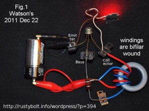
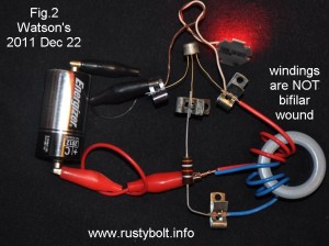
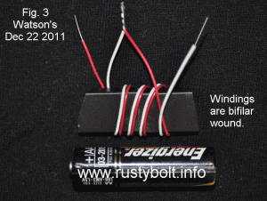
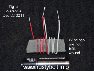
We can use heavier wire, but then the coil gets too large and bulky, and it costs more.  Instead we wind the coil on a core made of ferrite, which concentrates the magnetic field, increases the inductance, and allows us to use a much shorter length of wire.  This ferrite core can be a toroid (small donut), a rod or bar (see Figs 3 & 4), or a piece that looks like a link of a chain, but a square loop instead of a loop with rounded ends.  With the rod or bar, the magnetic field is concentrated in the core, but it must get from one end of the rod or bar to the other end, so it has to go through the air.  We can get a coil with the same inductance but shorter wire by using a core that has ferrite from one end of the coil to the other end, and looks like a chain link.  The coil is wound around one leg of the chain link, and the magnetic field goes through the ferrite link to the other end of the coil.  We can take out the squareness of the chain link core, and we then have a shape that looks like a donut or toroid as it’s called (see Figs 1 & 2).  This gives us a short magnetic path, a lot of inductance in a small package, and the windings can have a short wire length and very low resistance.

Back to the coil.  The wire can be wound bifilar, or it can be wound as two separate windings on the same ferrite core (see the attached pictures).  In the pictures I reduced the windings to just a few turns so that it can be clearly seen how they are wound.    One picture (Fig.1) shows the working Joule Thief with the windings wound bifilar, the other picture (Fig.2) shows the windings wound next to each other.  They are the same electrically to the Joule Thief.

In the Figs 2 and 4 you can see that both windings are wound in the same direction, as if the connection point is ignored and the turns are the same coil.  If we ignore the connection point and treat the windings as if they are one single winding, we can measure the AC voltage between the ends and we find that it is twice what it would be if measured from the connection point to either end.  In either case, the windings must be connected so they are in series, and the voltages of the two windings add.  If you measure the AC voltage from the end of one winding to the other, it will be twice as much as when you measure from the connection point of the two windings to either end.

The other  important point is that the coil has to store energy in the magnetic field.  This energy is from the current when the transistor is turned on, and when the transistor turns off, it has to go somewhere because the transistor suddenly seems to have been disconnected – it’s as if it isn’t there.  The LED is still there, so the stored energy causes the voltage to rise, and when the voltage gets to the forward voltage of the LED, current starts to flow through it.  The stored energy is dissipated in the LED, and the LED puts out light briefly.

One more thing: the amount of energy stored is equal to the current squared times the inductance, divided by 2.   The important point to remember is that if we double the inductance (wind more turns on the coil), the energy stored will increase.  But the wire has resistance, and the current will decrease.  If the current decreases to 1/2, then the energy stored will be 1/2 squared or 1/2 times 1/2 or 1/4.  Looking at what has happened, we are worse off.  It would be better to reduce the inductance by reducing the amount of wire on the core, which will reduce the resistance and allow more current to flow.  If we reduce the wire resistance to 1/2, then the inductance is reduced, but twice as much current can flow.  The energy stored is twice as much current squared or 2 times 2 or 4 times as much energy as before.  The inductance is less and causes less energy to be stored but we still come out ahead because the energy stored is 4 times the current.

We have to remember that with less inductance, the frequency the Joule Thief switches will increase.  There are losses in the ferrite core and in the transistor and in the LED.  These losses rise as the frequency increases, and will eventually become greater than the gains in energy storage.  We need to find a balance where we get enough energy storage, good efficiency and any magnetic or radio frequency fields that might radiate from the circuit will not interfere with radio reception.  Most of the JT coils I’ve built give a frequency between 30 kHz and 300 kHz.  The higher the L (inductance), the lower the frequency and vice versa.  But the inductance is highly dependent on the ferrite material that makes up the core, with the high mu ( µ or permeability) ferrite giving the higher inductance with greatly reduced number of turns.  This is why in Figs 1 and 2 I can wind only 3 turns on the humongous core but it has 93 microhenrys, more than enough to work great with a JT.

© RustyBolt.Info/wordpress
CyberChimps