The Coil: Explanation The coil, the heart of t he Joule Thief, is somewhat mystical in that those that understand basic DC and AC theory do not understand how a coil works. I will admit that I am no expert on magnetic theory but one does not need to know magnetic theory in order to understand how the coil works or how a transformer works. I’ll try to avoid any magnetic theory or heavy math.
A Joule Thief coil has two windings, only one of which is needed to do the voltage boosting. This winding is commonly called the primary mainly because that is what the input winding is called in a transformer. The second winding, called a secondary in a transformer, is called the feedback winding in a JT coil, because it does not perform a function needed to boost the voltage, it just inverts the signal which is fed back to the base of the transistor to keep it switching on and off. The transistor inverts the signal coming into its base, therefore the coil must invert it a second time in order for the feedback to be positive, and cause the circuit to oscillate on and off.
Basic Single Winding Inductor Let’s use a singe winding coil, also called a choke or inductor as an example of how a Joule thief boosts the voltage. We have a circuit that is a coil and a LED in series, with one lead of the coil connected to the positive of the 1.5V battery and the cathode lead (flat spot) of the LED connected to the negative. No current flows and nothing happens because the battery is only 1.5V and the LED requires 2V to 3.4V to conduct and make light. We put a push button switch in parallel (across) the LED leads.
Every time we press the push button, current flows from the positive through the coil and switch to the negative. In a short time the current builds up in the coil, storing energy. We release the push button, and the current flow is stopped, but the energy in the coil must find somewhere to go, so it tries to continue flowing, but the switch is no longer closed. The voltage across the coil rises, until it reaches the forward voltage of the LED, and the current then starts to flow through the LED until the energy has dissipated, and the LED makes a brief but bright flash of light.
But we want the LED to keep on producing light, so we press and release the pushbutton switch rapidly and the LED flashes quickly come, one after the other. This quickly gets tiresome on the finger pressing the pushbutton.
We remove the pushbutton and replace it with a transistor, with the emitter connected to the negative and LED cathode (flat spot) and the collector connected to the coil and other lead of the LED. Now we have a transistor that can switch so rapidly that the eye can’t see it, and the LED looks like it is continuously on. But we need to feed back some of the energy from the coil to keep the transistor switching. We wind another feedback winding over the original coil, and connect it so that the feedback to the transistor’s base lead is positive feedback. We connect one of the feedback winding’s wires to the positive of the battery, and the other lead to one end of a 1000 ohm resistor to limit the current to the base to a safe level.
Now when the battery is connected, the LED lights brightly and the circuit keeps switching the transistor on and off tens of thousands of times a second. It’s as if an invisible finger is pressing that pushbutton switch at more than ten thousand times a second.
Coil Winding There are several ways to wind the coil, all of which will do the job adequately. An easy way to wind two windings is to wind both wires at the same time. This is called a bifilar winding. We can take 20 feet of telephone wire, which has two 24 AWG solid conductors, and wind this onto a AA cell. It will have about 60 turns, and then we remove the AA cell and tie this coil in a few places with some wire ties or tape to keep it from unwinding. We connect this up just like any other Joule Thief coil, and it works, the LED lights up. But 20 feet of 24 AWG wire has about a half ohm of resistance, which causes a loss of power as the current passes through it, and causes a loss of efficiency; less of the power gets to the LED.
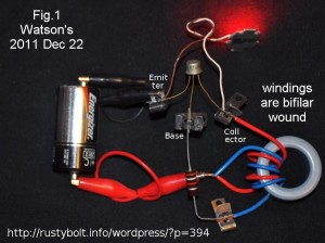
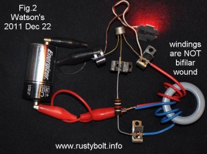
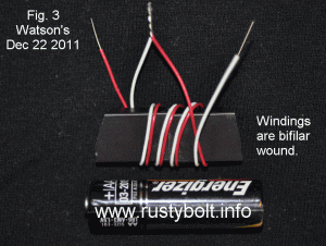
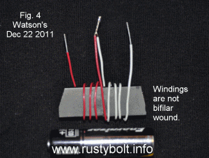
We can use heavier wire, but then the coil gets too large and bulky, and it costs more. Instead we wind the coil on a core made of ferrite, which concentrates the magnetic field, increases the inductance, and allows us to use a much shorter length of wire. This ferrite core can be a toroid (small donut), a rod or bar (see Figs 3 & 4), or a piece that looks like a link of a chain, but a square loop instead of a loop with rounded ends. With the rod or bar, the magnetic field is concentrated in the core, but it must get from one end of the rod or bar to the other end, so it has to go through the air. We can get a coil with the same inductance but shorter wire by using a core that has ferrite from one end of the coil to the other end, and looks like a chain link. The coil is wound around one leg of the chain link, and the magnetic field goes through the ferrite link to the other end of the coil. We can take out the squareness of the chain link core, and we then have a shape that looks like a donut or toroid as it’s called (see Figs 1 & 2) . This gives us a short magnetic path, a lot of inductance in a small package, and the windings can have a short wire length and very low resistance.
Back to the coil. The wire can be wound bifilar, or it can be wound as two separate windings on the same ferrite core (see the attached pictures). In the pictures I reduced the windings to just a few turns so that it can be clearly seen how they are wound. One picture (Fig.1) shows the working Joule Thief with the windings wound bifilar, the other picture (Fig.2) shows the windings wound next to each other. They are the same electrically to the Joule Thief.
In the Figs 2 and 4 you can see that both windings are wound in the same direction, as if the connection point is ignored and the turns are the same coil. If we ignore the connection point and treat the windings as if they are one single winding, we can measure the AC voltage between the ends and we find that it is twice what it would be if measured from the connection point to either end. In either case, the windings must be connected so they are in series, and the voltages of the two windings add. If you measure the AC voltage from the end of one winding to the other, it will be twice as much as when you measure from the connection point of the two windings to either end.
The other important point is that the coil has to store energy in the magnetic field. This energy is from the current when the transistor is turned on, and when the transistor turns off, it has to go somewhere because the transistor suddenly seems to have been disconnected – it’s as if it isn’t there. The LED is still there, so the stored energy causes the voltage to rise, and when the voltage gets to the forward voltage of the LED, current starts to flow through it. The stored energy is dissipated in the LED, and the LED puts out light briefly.
One more thing: the amount of energy stored is equal to the current squared times the inductance, divided by 2. The important point to remember is that if we double the inductance (wind more turns on the coil), the energy stored will increase. But the wire has resistance, and the current will decrease. If the current decreases to 1/2, then the energy stored will be 1/2 squared or 1/2 times 1/2 or 1/4. Looking at what has happened, we are worse off. It would be better to reduce the inductance by reducing the amount of wire on the core, which will reduce the resistance and allow more current to flow. If we reduce the wire resistance to 1/2, then the inductance is reduced, but twice as much current can flow. The energy stored is twice as much current squared or 2 times 2 or 4 times as much energy as before. The inductance is less and causes less energy to be stored but we still come out ahead because the energy stored is 4 times the current.
We have to remember that with less inductance, the frequency the Joule Thief switches will increase. There are losses in the ferrite core and in the transistor and in the LED. These losses rise as the frequency increases, and will eventually become greater than the gains in energy storage. We need to find a balance where we get enough energy storage, good efficiency and any magnetic or radio frequency fields that might radiate from the circuit will not interfere with radio reception. Most of the JT coils I’ve built give a frequency between 30 kHz and 300 kHz. The higher the L (inductance), the lower the frequency and vice versa. But the inductance is highly dependent on the ferrite material that makes up the core, with the high mu ( µ or permeability) ferrite giving the higher inductance with greatly reduced number of turns. This is why in Figs 1 and 2 I can wind only 3 turns on the humongous core but it has 93 microhenrys, more than enough to work great with a JT.


