default

2011-01-07 JonnyDavro’s Joule Thief, Power Xfmr Drives CFL

I was watching JonnyDavro’s Joule Thief driving a power transformer, which is used in reverse to step up the voltage to drive a CFL tube.  He shows the schematic, and later says that the unlabeled transistor is a BD139.

I added a comment, saying “What amazes me is that you’re getting these high voltages at points that are very sensitive to HV. The emitter to base junction is rated for a max of 5V (reverse), yet you haven’t fried the transistor yet. Especially considering that the maximum power for a BD139 is only 8 watts! I would put a LED across the emitter to base, cathode to base, just to protect the junction from excessive reverse voltage.”

I said this because the voltage across the emitter to base must never exceed 5 volts in the reverse direction.  I explain why this important in my earlier blog.  It is important.  Two ways of protecting the junction, as I explain below.  A diode can be put in series with the base, so that the base current must pass through both in the forward direction.  If the current tries to pass in the reverse direction, both the diode and E-B junction will be reversed and the diode will block it up to the point where its reverse voltage is exceeded, which could be a hundred volts or more for some diodes.  The one drawback with doing this is that the forward voltage across both junction and diode is 1.2V or more, which is too high for a Joule Thief with a supply of only 1.5V.

The other way to protect the junction is to put a diode in parallel with the E-B junction, so that (for NPN transistor) the cathode or banded end of the diode is connected to the base, and the anode is connected to the emitter.  If the negative voltage across the E-B junction exceeds 0.6V, the diode will conduct and shunt the current away from the E-B junction.  The disadvantage of this is that the diode adds a small amount of capacitance to the junction.  But this does not affect the Joule Thief, so we will use this diode to protect the junction.  We can change the diode to a red LED to let us know when and how much the reverse voltage is by how bright it lights up, so it serves a dual purpose.

Using a diode in one of these ways to protect the transistor will prevent damage, and it is important.  When a transistor is used as a switch, another fault that can occur is the collector becoming forward biased.  For a NPN transistor, that means the collector goes negative in relation to the emitter.  In some power MOSFETs there is a high current diode connected between source and drain, with cathode connected to the drain (for N channel).  This conducts if the voltage reverses polarity.  A diode can be put across a power transistor in a similar manner to protect it from reverse polarity.

In the vlog he said that the relay was chattering.  I commented that the relay is telling him that it doesn’t like AC.  He replied that it was a 12VDC relay and that no harm will come to it. I agree as long as the high voltage across its coil doesn’t arc over at some point.  What I heard was the relay chattering – it was not a periodic noise like a buzz.  This may be telling him something.  One would think that if the circuit is oscillating, the sound would be a buzz, but if the sound was a chatter, something else was happening, something erratic.  It could be a quirk of that relay, or it could be something in the circuit that was not intended to happen.  Anyway, it’s just a thought.

default

2012-01-06 Current Sense Resistor for Joule Thief LED

The first thing that comes to mind when the experimenter wants to find out how much current is flowing through the LED is to measure it with a DMM set to read milliamps.  This works okay if the LED is connected in series with a current limiting resistor.  The DMM will add maybe 10 ohms to a resistance of several hundred ohms, so it is hardly noticeable.  But when the 10 ohms is added to a circuit that is driving the LED with pulses, then 10 ohms may affect the circuit and skew the readings.  For example, if the circuit is driving the LED with 100 milliamp pulses, then the voltage drop across 10 ohms is…  1 VOLT.  Instead of 3 volts across the LED we have 4 volts across the LED and internal resistor.  The result is a current reading which is too low and far from what it would be without the DMM.

What to do?  Well obviously lowering the DMM’s internal resistance would help. If we look at what is going on inside the DMM when it is reading milliamps, we see a voltmeter across a known resistance, known as a shunt.  Well, we can move that known resistance outside of the DMM, and use the DMM as a voltmeter to measure the voltage drop across it and calculate the current.  Instead of 10 ohms internal resistance, we use a 1 ohm resistor, and measure the voltage across it.  Since 1 amp through 1 ohm gives 1 volt, then 100 milliamps through 1 ohm will read 100 millivolts.  Likewise 100 millivolts means there is 100 milliamps flowing in the resistor.  And if the resistor is in series with the LED, there is 20 milliamps flowing through the LED and resistor when there is 20 millivolts across the resistor.

Since 1 ohm is 1/10 of the internal 10 ohm resistor, the circuit is disturbed much less, and the reading is much closer to what it would be without the resistor.  This 1 ohm resistor is known as a current sensing resistor, even though it would be called a shunt if it were inside of the DMM.  We can temporarily put this resistor in series with the LED, or even leave it there permanently if it doesn’t affect the LED too much – 20 milliamps times 20 millivolts is 0.4 milliwatt, which is a very small loss of power in this resistor

Back to experimenting….

default

2012-01-05 Watson’s 3 LED Ring Oscillator

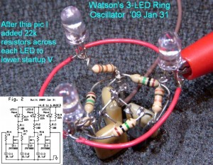
This simple circuit acts somewhat like the LED Fader in that the LEDs do not turn on and off abruptly, however since the typical speed of the ring is faster than the fader, it’s harder to tell the turn-on and turn-off.  It’s a fun circuit to build because of its simplicity and good visual effects.  The circuit consists of three stages, each stage is identical to the others (see the schematic in the picture).

Each stage is simple: an RC low pass filter, which is connected to the gate of a 2N7000 MOSFET.  The LED and current limiting resistor are connected to the drain, and the source is connected to common negative.  The low pass filter has the effect of shifting the phase of, or delaying the signal as it passes through, so the signal gets enough delay through the whole circuit to sustain oscillation.  The values of the resistors and capacitors determine the speed of the LEDs turning on and off (for even speed, the values should be the same for all stages).

Since the MOSFET does not need any current to the gate, the resistors can be any value up to megohms or millions of ohms.  This allows us to use smaller capacitors, so the 0.1 uF plastic capacitors will work well with 1 meg resistors, as shown here.  The 2N7000 requires about 2 volts to turn the gate on so the minimum supply voltage has to be the LED forward voltage (2 volts for red, 3V for blue) plus the gate voltage, or 5 to 6 volts.  The supply voltage can be lowered somewhat by putting a resistor across each LED (I used 22k).

The circuit will work with more stages, however the number of stages must be an odd number: 3, 5, 7, 9, etc.  I built a 9 stage ring oscillator, but I later realized I could get a good enough effect by connecting every third LED in series and use only three stages.  Of course the supply voltage has to be higher.

I tried to build a similar circuit using regular BJTs (bipolar junction transistors), but I couldn’t get it to oscillate.  I read that they require a pushbutton switch across one of the capacitors to short it out and get the oscillations to start, but I didn’t like that it had to have someone start it up.

Thanks to Bill Sherman for leading me to this circuit.  I blogged this before, I’ll have to see if I can find that blog.

Back to experimenting…

default

2012-01-04 Transistor is Vulnerable in a Joule Thief

Most silicon transistors have an emitter to base reverse voltage rated at 5 volts maximum, with some transistors rated as high as 6 volts.  Old germanium transistors were higher than this, but when the manufacturers began to make silicon transistors, they apparently gave up having a higher emitter to base reverse breakdown voltage so they could gain performance in some other area.  As a result, almost all modern silicon transistors are rated for 5 or 6 volts.

What happens if this voltage is exceeded, and the emitter to base junction breaks down and conducts current?  I thought that the junction would act as a zener diode and as long as the power didn’t cause overheating, it would not do any harm.  Then one day someone in the Usenet Newsgroups said that when the emitter to base junction breaks down and conducts current, it permanently damages the transistor by reducing its current gain.  I didn’t believe this, so I put a transistor on a power supply and ran just a few milliamps through the emitter to base junction in the reverse direction for a few minutes.  I measured the transistor’s current gain before and after I did this, and I found that the current gain afterwards was much lower than it was before, something less than half of the original current gain.

I was really surprised.  I had no idea that the transistor’s current gain would be affected by such a low power and small current.  But one has to remember that most transistors are used as amplifiers and their emitter to base junction is never reverse biased, so there is no chance of this damage happening.  When a transistor is used for switching, the E-B junction can be sped up by putting reverse voltage on it.  Or if a transistor is used in a circuit with inductance, the inductor can put reverse voltage on the E-B junction.  This is the case with the Joule Thief.

The conventional Joule Thief runs on only 1.5V, and the highest voltage anywhere in the circuit is across the LED, which is less than 5V with a single LED under normal conditions.  The feedback winding is typically the same number of turns as the primary, so whatever voltage is on the primary is reflected in the feedback winding, even though the polarity is reversed.  This means that when the primary’s peak voltage is 5V, the feedback’s peak voltage is a negative 5V.

As long as the LED is in the circuit and puts a limit on the maximum coil voltage, the transistor’s emitter to base junction will not have to handle more than 5 volts.  If the LED is removed or there are two or more LEDs in series, the voltage across the emitter to base junction will increase, because the feedback winding reflects the voltage in the primary.

The feedback winding is connected to the battery through a resistor, so it will have 1.5 volts added to its voltage.  In other words, if the peak voltage across the feedback winding is negative 5V, then the voltage relative to negative is a negative 3.5V, after adding the battery voltage.  The peak voltage across the feedback winding would have to exceed -6.5V for the negative voltage on the base to exceed -5V.  When we design the JT circuit we want to make sure that the negative voltage on the base never exceeds -5V.

We can allow the peak voltage across the primary winding to go higher than 6.5V if we change the feedback winding so it has less windings than the primary.  If the feedback winding has half as many turns, then the voltage across the feedback winding will be half of the primary voltage.  But since most transistors used in a conventional JT can handle only 20 to 50 volts, we can’t allow the primary to feedback turns ratio to be too high because the primary voltage would then be above the transistor’s collector breakdown voltage.

If the output voltage must be high to drive multiple LEDs, then it is easy to wind a third high voltage winding on the coil, which will have many turns of fine wire. This voltage will be ten times higher than the primary if it has ten times the number  of turns.  Of curse the current will be proportionately lower, too.

Back to experimenting…

default

2012-01-03 Joule Thief FAQ 1

I received a message asking several questions about the Joule Thief.  The asker asked to be explained in layman’s terms, so I’ll try to keep it understandable.  First off, I do not use a Spice program to simulate the circuit.  I used LTSpice a few years ago, but not any more.  Why should I when it takes a few minutes to connect five parts and I can then get the Real Thing?  Also, always keep in mind that a Spice program uses a component that is not like a Real World component.  A real world transistor might have a current gain of from 100 to 300, or even a wider spread, 100 to 500. I don’t think LTSpice gives you that kind of real world simulation.

Q1.  How did I measure the efficiency of a Joule Thief?

A1.  I used the supply voltage times the supply current to get input power (the regulated power supply is set for 1.5V and its meter tells me the current).  For example 1.5V times .075 A (or 75 milliamps) equals .1125 watts.  I measured the voltage across a 1 ohm current sense resistor in series with the LED. For example .017V times 1 ohm gives .017A.  I multiplied this current times 3.3V for the LED forward voltage to get the output power to the LED. For example .017 times 3.3 equals .0561 watts.  Then I divided the output power by the input power to get the efficiency. For example .0561 divided by .1125 equals .4987. Multiply this by 100 percent gives 49.87 percent efficiency.

Q2.  Do you have any recommendations on measuring efficiency, with a DMM, without a regulated power supply?

A2.  You can measure the battery voltage with a DMM, at the point where the battery connects to the circuit.  Another 1 ohm resistor can be used in series with the battery to allow the DMM to measure the voltage across it and then get the current, same as above example.  We have to remember that there is about 100 mA supply current, and that means about 100 millivolts or 1/10 volt drop across this 1 ohm resistor.  That’s about 7 percent of the 1.5V supply, and it’s too  much V drop.  We can lower this by using a lower value resistor.  A 1/2 ohm resistor will give about 50 millivolts drop, which is better.  I used 1/10 ohm resistors, which give only 10 millivolts drop.  That’s less than 0.7 percent of the supply voltage.

Q3.  I know that the 2N3904, 2N2222 and 2N4401 are all different types of NPN transistors but what particular characteristic makes one more efficient over the other (in this application)?

A3.  The transistor should have high current gain at high currents and very low collector voltages.  A maximum collector current of 500 milliamps is a good starting point, the more the better.  It must also have a low Vce(sat) at high currents. I look at the graph and see if the transistor’s collector saturation voltage is 1/4 volt or less at currents of at least 250 mA, but hopefully at closer to a half amp.  The BC337 does not have any graphs for Vce(sat) but every BC337 that I have used can handle current better than a PN2222A or 2N4401, so I recommend it for JT use.

Q4.  You also mentioned the JT eval website on scribd, so you may or may not be able to answer these questions but: http://www.scribd.com/doc/35050054/Joule-Thief-Eval  1.  What exactly is a figure of merit? Is this just another name for efficiency?

A.  I cover the stuff in this document in my recent blog.

Q5.  How does the capacitor (base capacitor from the JT eval) allow the transistor to switch on and off faster? What are the consequences of this and why?

A5.  The author explained this in the document at the link you gave.  But I have my opinion about that, and it is covered in my recent blog (see the link above).

Thank you for the thoughtful and thought provoking questions.  I hope my answers are correct, or if not, reflect what results others may get.  As with the other author, his mileage varied because of his situation.  Your mileage may differ if you do the same experiment.

default

2012-01-02 Joule Thief with Rectifier and Filter Capacitor

I often read where people add the rectifier and filter capacitor between the coil/transistor and the LED.  They claim that it increases the efficiency.  I just want to clarify what I see is happening as the Joule Thief is operating.  My observations are based on what I see on an oscilloscope connected to the JT, and other measurements.

In a JT, the coil stores the energy that has to go somewhere when the transistor turns off, and this gets transferred to the LED.  During this time the transistor is open, it as if it was disconnected, and it does not dump the energy to ground. If you add the Schottky diode and filter capacitor, the schottky does not increase the amount of energy in each pulse that comes from the coil.

When your JT is running, each pulse of energy from the coil starts at a low voltage and high current and gets transferred as a higher voltage at a lower current.  To my thinking it’s a pulse of energy, and whether you transfer it directly into the LED or through the diode and filter capacitor, which turns the pulses into filtered direct current, the energy from the coil is the same.  But the diode has a voltage drop and when you find the power by multiplying the current times this voltage drop, this is a loss of power that ends up heating the diode – it is wasted power.

There may be other factors, such as how the LED responds to pulsed DC and filtered DC.  The filtered DC could be brighter because of something that is caused by the LED’s response. But the way I see it is the LED is already a diode, and the circuit does not have to have a rectifier and filter capacitor to make it more efficient.

In my recent blog, I compared the conventional JT with my Supercharged JT, and gave the results of the actual light output measured with the luxmeter.  The SJT is much more efficient, and is a simple circuit using inexpensive parts.

One might ask why I don’t compare the light output of the SJT with a conventional JT with Schottky and filter capacitor.  I can’t see why I would need to because I believe the SJT has to be more efficient because of the lower current and therefore lower loss in the (Schottky or regular) diode.

Update Jan 6 2012 Comparison W & W/O Schottky & Filter Cap

I used a slide switch to switch the LED between the conventional (without) and the 1N5817 Schottky diode and filter capacitor.  First, the components I used.  The coil was a 1/2 inch high mu core with 13 turns solid twisted pair from a cat5 cable.  The LED was blue, with a 1 ohm current sensing resistor in series.  The transistor was a BC337-25.  The filter capacitor was a 100 uF, and the supply had a 100uF bypass cap.  The supply voltage was 1.5V for both tests.

The LED current was 19.7 mA and the supply current was about 95 mA without Schottky.  When I switched to the Schottky and cap, the LED current went up to 24.7 mA, and the supply current went up to about 98 mA. This is a substantial gain in brightness with only a small increase in supply current.  This agrees with the claims by others that the Schottky diode and filter cap increase the brightness of the LED.

However I must remind everyone that my Supercharged Joule Thief does even better with easier to get parts and less expense.

Update Jan 10 2012 – QS left a comment; Thank you.  I’m happy to see he is somewhere, because Bill and I were seeing his emails bounce because his email inbox was full.

default

2012-01-02 Transistors for a Joule Thief

Joule Thief Special  There are thousands of different types of transistors, made by hundreds of manufacturers.  But it takes a special kind of transistor to give good performance in a Joule Thief.   The transistor should have high current gain at high currents and very low collector voltages.  A maximum collector current of 500 milliamps is a good starting point, the more the better.  Most transistors have a loss in current gain as the current increases past a certain point; for small signal transistors that point is about 100 mA or 1/10 of an amp.   The datasheet for the (Vishay) BC337 shows the current gain beginning to roll off before 100 mA, but by the time the current gets to a few hundred mA, the gain is still 200, so it still makes a good JT transistor.  The 2N3904 datasheet (Motorola or On Semi) graph shows the gain at 10 mA is around 240, but at 200 mA, it has dropped drastically to about 30.  This is a poor choice for a JT.

The JT transistor must also have a low Vce(sat) (collector to emitter saturation voltage) at high currents. I look at the graph and see if the transistor’s collector saturation voltage is 1/4 volt or less at currents of at least 250 mA, but hopefully at closer to a half amp.  The BC337 (Vishay) shows the Vce(sat) rising above 0.25V when the collector current gets up to more than a half amp.  Every BC337 that I have used can handle current better than a PN2222A or 2N4401, so I recommend it for JT use.  The same Motorola datasheet for the 2N3904 shows that the Vce(sat) rises above 0.25V when the collector current is about 75 mA, and at 200 mA it is over a half volt, and that is very bad, because it is wasted power heating the transistor and not lighting the LED.

The following is a table of transistors used in the same JT, and the supply and LED currents that I measured.  The 2N3904 is very close to the BC550 performance.


Recommended:

2N4401, PN2222A, BC337, BC338, SS8050

Not recommended:

BC547 series, 2N3904 (the JT exceeds its maximum collector current of 200 mA.)

default

2012-01-01 Back in early days of electronics – Watson’s Winky

My watsonseblog dated 2007 Jul 14


Back in the early days of electronics, they would assemble several neon lamps with 1 meg resistors and 1 uf caps in a box, along with a 90V B battery. The lamps would flash in random patterns. These were called a “Do Nothing Box”. I guess this is my version of a Do Nothing Box.

I came across a project at W. D. Sherman’s site that is similar to a project I built a few years ago. I used a PSO (Phase Shift Oscillator) to drive LEDs so that they turn on and off gradually, not abruptly as the usual flasher does. The PSO uses three RC networks, each delaying the signal 60 degrees, for a total of 180 degrees delay between the collector and base of a transistor. Along with the 180 degrees in the transistor itself, this gives 360 degrees total and this positive feedback causes the circuit to start oscillating, putting out a sine wave.

I had long thought about putting an additional transistor between each of the RC networks, and driving a LED with that transistor. I had seen similar circuits in circuit handbooks and other texts, so the idea wasn’t new. But I had never used an enhancement mode MOSFET for the transistor. Since the 2N7000 enhancement mode MOSFET acts like a vacuum tube and doesn’t draw any current on the input, the biasing is much easier than with a regular BJT transistor. And with the very high input impedance, small capacitors below 1 uF, and megohm plus resistors can be used. But it does require more than 2VDC at the gate to turn on the 2N7000.

I built the circuit at Sherman’s site with the following changes. He didn’t specify the LED color, but I used red LEDs. I used 5 sections instead of 7. I used 470k resistors instead of 499.9k. I used 100 ohm resistors instead of 120 ohms. And I changed the most important part, the timing capacitor, from 4.7 uF to 0.33 uF or 330 nF. I first used 1 uF, but it was still too slow, so I changed them to 0.33 uF. I think they could be even smaller, 0.22 uF would be better. Or use the more common value of 0.1 uF and change the 499k to 1 meg.

I used three AA cells for 4.5VDC power. The circuit works well, each LED fading out and the next one gradually brightening up. The red LEDs drop about 2V, and it requires at least 2V to turn on the 2N7000, so the circuit is limited to operation above 4VDC supply voltage – below that it just quits. The total supply current varies with the LED brightness, so the supply current is constantly changing in the 50 to 100 mA range. I would say that three 1.5V cells is too low a voltage, it should be a minimum of 5V and preferably 4 cells for 6VDC.

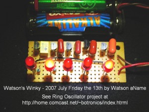
And for LED colors such as green and blue, 6VDC may not be high enough. Or 2 or 3 LEDs can be connected in series, and a 9VDC supply can be used. If three sections are used, then multiple LEDs per section could be used in series to give the effect of the flashing lights around the edge of a marquee. Right now all of the LEDs are in a line (see picture), but I may try putting them in a circle. I think 9 LEDs around a circle at 40 degrees apart would give a nice effect. I may try two concentric circles, with 9 LEDs on the outer one and maybe 5 LEDs of a different color in the inner circle. And connect them up so they counter rotate. It’s soothing to watch the LEDs go through their patterns of oscillation. One could sit and watch them in a darkened area to relieve stress. Or just put them on a shelf and let people ask what they are for!

I was staring at the blinky LEDs today, Saturday, and it seemed that they were off longer than they were on. I’m still running it from three AA cells at about 4.5VDC. The 2V drop across the LEDs limits the voltage at the gates to 2.5V or less and that seems to be the reason why it’s unable to operate below 4V and why it’s operating marginally now at 4.5V. All it needs is to have a bit higher voltage across the rest of the circuit when the LEDs are not conducting. Well, I had an idea that if I put a resistor across each LED, the voltage at the LED cathode could be pulled up to nearly the supply voltage when the FET is not conducting. So I put a 22k across one LED and it really did make a difference. I then warmed up the soldering iron and put a 22k resistor across all of the LEDs, and it made an obvious difference – the LEDs stay lit longer. Now it will still function down to 3VDC. The 22k is a very small fraction of the 499k with which it’s in series when the LED is off, but it draws negligible current when the LED is on. If you think the effects it causes are too strong, you can increase the value to over 100k and as it goes higher, the effect is less noticeable until there’s no difference with or without the resistor. I’m guessing that this may be when the resistors are nearing a half meg or more. But by adding these resistors, the circuit will operate below 4V, and the LEDs will also speed up a bit and stay on longer. They will allow you to leave the 1.5V cells running until they are down to 1V, which gives many more hours of operation on a set of 3 cells.

Back to experimenting…

default

2011-12-31 Joule Thief, FET Only

Happy New Year!  My watsonseblog dated 2009 Jan 1
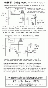
Joule Thief, FET Only is the topic. In April 2005 I built a Joule Thief (circuit is in my blog and at the bottom of this webpage) that used both a 2N3904 BJT and a 2N7000 MOSFET, with the 2N3904 starting the circuit and the 2N7000 then supplying most of the current. It’s not a complex circuit, but it really doesn’t need the 2N3904 after it gets started and the 3.3 volts across the LED is then used to supply the gate bias to the 2N7000. The 2N3904 won’t start at a supply voltage less than 0.6V, but it could be replaced with a germanium transistor which operates easily down to 0.2V. But germanium transistors are getting very rare, and they are very temperature sensitive, which is probably why silicon transistors have replaced them almost completely.

Theoretically Speaking..
If a MOSFET had a gate that would operate below a few volts, then it alone could be used for a Joule Thief or any other low voltage circuit from a single 1.5V cell. But the gate of almost all MOSFETs requires more than 1.5V to turn it on.. With a Joule Thief, though, once it gets operating, the boosted and rectified voltage can be used to supply the gate bias.

And remember that this is a MOSFET, which means the gate is insulated and does not draw any current from the circuit. The base of a BJT, on the other hand, only operates with a small current flow. If we can raise the voltage at a MOSFET’s gate to turn the MOSFET on, there will not be any current flowing thru the gate. The feedback will have to charge and discharge the gate to source capacitance as the gate’s voltage changes, but this capacitance is almost purely reactive, with almost no resistance, so it doesn’t dissipate any power.

Thus, I came up with the idea that I could make the MOSFET work at very low voltages by putting a voltage source in series with the gate, so that it is “prebiased” closer to being on when the circuit is powered up. I used a 1.5V alkaline button cell to add 1.5V to the gate when the circuit is not powered up, and when the 1.5V power is applied, the gate will have a total of 3V on it, which is enough to get the MOSFET to run by itself. Since the gate draws no current, the button cell should last for as long as its shelf life, which could be several years.

I read about the Zero gate threshold MOSFET. I downloaded the spec sheet for the ALD zero gate threshold ones, and found that the Rds(on) is 500 ohms at max (but probably a few hundred typical). What this means is that at a fraction of a volt, the most they will conduct is a milliamp, so if they are used in a converter, they will only put out a fraction of a milliwatt. But that’s okay, one would use this MOSFET to boost up the voltage to 5 or more V, then use that at very low current to bias the gate of the power MOSFET.

So I did some more searching for a better solution and came up with the Supertex line, specifically the TN0702N3, which is $.63 each if you buy 100. They are low gate threshold V, 0.5 to 1V, which isn’t as good as the ALD parts, but a lot better than the 2N7000. The Rds(on) is a lot lower than the 2N7000’s 5 ohms. I ordered them from Mouser, along with some button cell holders.

The Circuit
I built the circuit shown at the top in the schematic, and I used a coin cell holder to hold the much smaller button cell. It is much too big, but the holder’s spring holds the button cell good enough to make contact. I put a 100k resistor in series with the button cell’s + lead, and I measured the voltage across it while the circuit was operating. On the lowest V range, the voltage read 0.0V, meaning that there was no current flowing through the button cell.

The T1 toroid has to be wound different than the usual Joule Thief. The feedback winding has to put out a higher voltage to the gate, at the gate’s very high impedance. This means the feedback winding has to have many more turns than the primary winding. I didn’t count the turns, but the feedback winding has ten times the inductance of the primary, so it has about 3 or 4 times the number of turns. The feedback winding should be able to develop enough voltage to cancel the 3VDC that is on the gate and turn the MOSFET off. I don’t know if this is enough turns, it might work better with 5 times or ten times as many turns. That’s another area of experimentation that I’ll have to try.

RESULTS
As it is, it works very well. With 1.5VDC supply, the circuit draws about 80mA from the supply, puts out 13.2mA to the LED, and runs at 71kHz. I kept lowering the supply voltage until the LED went out at below 0.4V. It also started up at 0.4V, which is better than a silicon BJT transistor, but not quite as low as a germanium BJT. But this may be changed by increasing the button cell voltage and/or increasing the number of turns in the feedback winding.

Update — a few hours later. I wound another two feet of 32 AWG wire onto the core and connected this and the original feedback winding in series aiding. (the aiding is important — if they’re opposing, one will cancel out the inductance of the other, and the total will be less than either winding). Their total inductance is 2.8 millihenrys. I’m estimating that the primary-feedback turns ratio is about 1 to 5 or a bit more. Now my ‘MOSFET Joule Thief” has increased LED current to 15mA, supply current to 110mA, and a frequency of about 65kHz. But the really cool part is the circuit will now start up at below 0.3V, around 0.27 volts supply voltage. This is getting very close to what the germanium transistors will do. And at 0.5V, where the regular transistor can barely light the LED, this circuit can still put out a substantial amount of light, much more than the standard BJT circuit, in my experience.

Further results..
I removed one turn from the primary, making it ten turns. The supply current went down a few mA, the LED current went down to 14.7mA, and the frequency went up a bit to 69kHz. It starts up at about 0.27 volts, not much difference from before. Even though the turns ratio got greater, the LED current went down, so I think I’m heading in the wrong direction.

I put a second MOSFET in parallel with the original 2N7000, and it made a significant difference. The supply current went up to 175mA, the LED current went up to 19.7mA, and the frequency was 60kHz. The increase in the LED current was welcome, but it came at a much higher supply current and a lower efficiency.

I put a short across the 0.1uF capacitor and the LED went out immediately (the 100k resistor is between the cell and the capacitor, so I’m not shorting the cell). This shows that the additional 1.5V is needed for the circuit to continue to run.

More Changes
I did some more experimenting with the circuit. I added a second button cell for 3V, and put a 470k trimpot across them, so I can adjust the voltage going to the 0.1 cap and then to the gate. I changed the gate bias voltage with the pot while monitoring the supply and LED currents. As I increased bias, the supply current increased a lot but the LED current went up only slightly. So I’m guessing that the on time of the FET is increasing, and letting the current go to waste. So I don’t think the bias voltage needs to be more than 1.5V. In fact, I can turn the pot down and the circuit will work with less than a volt from the button cells. I’ll be writing this up in my blog asap. I figure that the 470k pot’s drain on the button cells might discharge them in a year or so… 😛

I’ve still been playing around – er, experimenting with my circuit. I removed turns from the feedback winding. It was 5 or 6 times the turns of the primary, but now it’s down to about 2 times. The frequency went up from 60 or so kHz to about 100kHz, and the LED and supply currents have come down, but to increase them, I turned up the bias adjust pot. The LED current got up to 17mA, then when I went further, the supply current jumped to over 200mA and the LED current peaked at 20mA. I wonder why the thing jumps to so high a supply current (luckily my supply is current limited). I added back a few turns to the feedback winding and now the current jump went away. It might be that the gate bias is taking the MOSFET into the linear region, where it is conducting heavily but still oscillates.

Running on Empty…
Just for the halibut, I decided I wanted to find out if the 0.1 uF capacitor could hold the charge of the button cells by itself, and for how long. I disconnected the button cells from the capacitor, leaving only the capacitor, the feedback coil and the MOSFET’s gate connected, and the wiring between them. The LED continued to stay lit. I monitored the LED current through the 1 ohm resistor; it started out at 13.6 milliamps. As time went on, it dropped a tenth of a milliamp, then another tenth of a milliamp. After about an hour, it had dropped about 2 tenths and continued to drop. Six hours later it was down to 11.2 milliamps. It seemed to drop about a tenth of a mA every 20 or 30 minutes, so the capacitor is holding the charge very well. Unfortunately I can’t measure the voltage direcly because as soon as the meter touches the capacitor, it discharges through the meter!

Button Cell Holders?
I think I need to buy some 1 cell and 2-cell button cell holders. I’ve never seen one in any equipment; every button cell I’ve seen has been in a holder made into the plastic case of equipment. Maybe Google might be able to help. In my blog I previously described one I made out of a wood clothespin, which works okay but is much too big for a small MOSFET Joule Thief circuit. I’ve also described others I’ve made in my blog.

Well, I found some button cell holders here. Not quite what I expected, though, just a metal clip. But I found something really cool there too. Put your mouse cursor over the picture of the button cell holder and see what I mean. Cool! I don’t think I’ve ever seen that before. I’ll keep looking for something more substantial – besides the company sells the holder 30 to a bag, and like I’ll probably need a dozen in the next decade, I’d really like to find a smaller quantity. Not to mention that the company is halfway around the world, in England. Well, I found some 12mm button cell holders in the Mouser paper catalog, so I’ll have to order a few, and some white Seoul Semi LEDs while I’m at it. 😉

I ordered some 12mm button cell holders, both single and dual, from Mouser, $.99 each, USD. Oops, I already have some Seoul Semi 1W LEDs, so instead I ordered some Supertex N-channel, Enh mode MOSFETs, TO-92 pkg, low threshold, 0.5 to 1V. Cool! Mouser # 689-TN0702N3 bulk packaged, catalog P. 523. And a few Fairchild J105 JFETs, which are supposed to be able to handle 500mA. They’re used in the startup circuit in the Damaschke .PDF (google ‘damaschke thermopile’) about building a DC-DC converter that runs off a 0.3V thermopile.

Other Thoughts..
Another thought occurred to me. If you wanted to, you could make a “Joule Thief Squared”. What I mean is that the button cell could be replaced by a depleted AA or AAA cell, or even two depleted cells in series. Or even spent button or coin cells These would last until they dried up or leaked, since there is no current flowing through them. Just another way of stealing more Joules from spent cells – that’s what it’s all about. (This reminds me of my old calculators and I’ll have to spend some time writing a blog on that subject.)

Another thought: If we can make an electret microphone that uses a “battery” made by exposing a substance to an electric field, we should be able to make an electret with enough charge to put in a MOSFET circuit so that the gate would need much less voltage. Just like the button cell, it would add to the incoming signal to allow the incoming signal to turn the gate on at a fraction of a volt. In a way, this would be like a depletion mode MOSFET, however, the enhancement mode MOSFET would not be conducting with zero bias on the gate, as a depletion mode MOSFET does.

Another thought. If I could get the insulation so high that there would be almost no leakage, I could put a capacitor in series with the MOSFET’s gate, and charge the capacitor up to the required voltage to bias the gate just below turnon. Then with a signal of just a fraction of a volt, the MOSFET would be turned on. Since there is no current flowing in the gate, the capacitor would stay charged for a very long period of time — maybe months or years if the insulation was good enough. If a ‘super capacitor’ of, say, 1 Farad could be charged up and hold its charge for years, then it could be used in this circuit. The advantage here is that the voltage could be adjusted, in contrast to a battery, which is always at a fixed voltage.

I did some google searching and found that aldinc.com makes a zero gate threshold MOSFET, and it will work to below 0.2VDC. See this link for a circuit example. http://www.discovercircuits.com/H-Corner/verylowosc.htm Wow! Cool! You don’t even need a button cell!

I’m going to go back and rewind the toroid, or wind more turns in the feedback winding. Well, I just did that, and updated it above, with definitely positive results. Now the hole in the toroid is just about filled up. If I want to add more turns, I’ll have to get a bigger core, or use finer wire. I may remove a turn or two from the primary, which will increase the turns ratio, but the frequency will go up. That’s not a problem for the MOSFET. I’m wondering when I’m going to meet the point of diminishing returns.

Ideas From Others..
I corresponded by email with Quantsuff, and he came up with the nifty idea of using a DPDT switch to turn the circuit on and off, but also switching the 0.1uF capacitor from in parallel with the supply (to charge it up) to in series with the supply, thus giving the MOSFET gate a total of 3V at startup. Then after it gets going, the output to the LED is rectified by a diode, through a resistor, and back to the 0.1uF capacitor to keep it charged. It will then have the LED voltage minus the diode drop across it during operation, which is about 3 volts.

This is great, it eliminates the button cell. But one problem is the circuit always needs human intervention to start up. Take a solar powered yard light for example. At sunset, you would have to go to every one to turn them all on. Another concern is as the “MOSFET Joule Thief” runs down the battery, the bias voltage across the 0.1uF capacitor also goes down (from diode leakage), so I’d guess that this will adversely affect the performance.

This “flying capacitor” or “switched capacitor” charge pump circuit is used by many DC-DC converters, but it is switched electrically, not manually. National’s LM2751 and Maxim’s MAX1576 are two of many ICs that use this. Dave Johnson has a switched capacitor LED driver here. The idea is to double the voltage by charging the capacitor then putting it in series with the supply. With a similar circuit, one could draw a few microamps from a single 1.5V button cell and double, triple or quadruple the 1.5V at very low current to make enough voltage to bias the gate of the MOSFET.

In his email, Bill “Botronics” Sherman used a small solar cell in place of the button cell. That’s cool. But of course the circuit won’t start up in the dark. But then, this might have an advantage: you could start it up by shining a beam of light at the solar cell from a distance. The solar cell costs five bucks, so I don’t think that it would be cost effective to use one to turn off a circuit that cost 1/5th that much.

Back to experimenting…

default

2011-12-30 Joule Thief, High Efficiency, Supercharged

My watsonseblog dated 2009 Feb 19   These may be dupes or unfinished.

2009-02-19

Joule Thief, High Efficiency, #01 Supercharged

See the schematic and original blog here.

I have built several of these high efficiency ‘supercharged’ Joule Thiefs (SJTs) to try to optimize the parts values, especially the coil. I’m posting these SJT blogs to allow the reader to get better results when building a duplicate SJT. I’ll give info on winding the coil, wire size, etc.

This SJT used a toroid core from All Electronics, part number TOR-54 (they have since sold out). I put a single turn (piece of straight wire) through the hole in this core and it measured 0.08 uH (I measured several of them to get an average). This means it is a low permeability core, much lower than the usual ferrite RFI suppressor sleeves that I’ve used (compare that to the charcoal TOR-23 cores they sell, which have 0.48 uH per turn). It also means that I have to use more turns to get the inductance up to 100 uH.

I jumble wound three solid enameled wires, each 36 inches long, wound trifilar, i.e. all three at the same time. Two were 28 AWG, connected in parallel for the primary winding. The third was 30 AWG, for the feedback winding. I cut the three wires to length, and on one end I twisted all three together to allow me to thread the wires through the core. Afterwards I cut off the twisted part. Each winding measured 124 uH.

For Q1 in the Fig. 2 circuit shown in the schematic (see link at top), I used a BC337-25. The R2 was 820 ohms, D1 was 1N4148. C2 was 1000 pF. The LED was a cheapo white LED removed from a 9-LED flashlight. A 47uF tantalum was across the supply rails.

MEASUREMENTS
I connected it to a 1.5V supply, and measured the supply current at 50mA. The LED current was 21 mA. The freq was 224 kHz. The LED was very bright. I calculated the efficiency at 89 percent, which seems too high, however the circuit did have very low power consumption.

Observations
This coil was wound using .335mm wire for the two primary windings. This is actually slightly larger than 28 AWG, about 27.5 AWG. It’s taken from a fan motor winding made in Switzerland. I had to scrape the very tough insulation off the ends with a single-edged razor blade, and it took quite a bit of scraping.

I am trying to keep the coil inductance above 100uH, and with the TOR-54 this means using solid enameled wire. If I used plastic insulated telephone wire, I wouldn’t be able to get a long enough length on the core to get 100uH.

Back to experimenting…

© RustyBolt.Info/wordpress
CyberChimps