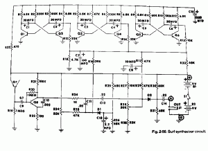
 A long time ago I came across this schematic of a Surf Synthresizer circuit. I remember reading something about this earlier, and I wanted to build one just to see if it actually worked. It’s a set of three astable multivibrators with their output voltages summed and low pass filtered, and the result is used to modulate the amplitude of a zener noise generator (actually it’s Q7, a transistor, with the emitter to base junction used as a zener). The bias on the diodes are used to modulate the amplitude. The astable MVBs run at less than 1 Hz, so their sum is a slowly varying voltage, similar to the patterns on the waves as they hit the shore.
Today, I think it would be much easier to simulate this circuit with a PIC or whatever microcontroller. The circuits could be easily simulated in software. I’m an analog type of person, so I tend to do things the hard way, and I would use solder as my programming language and build the circuit as shown in the not-so-clear schematic. The output is line level, for driving an amplifier and speaker. Thus in addition to this synth, I would have to build an amplifier, which sounds like fun. Or maybe I should just feed it into a mixer so it comes out of the speakers I use on my PC. Or maybe I should go out in the garage and dig out a pair of old speakers that I had long ago on an older PC. Probably the best idea, huh.
The junction of Q7 breaks down at somewhere between 6 and 10V, so a single 9V battery won’t be enough to power this circuit. They used two 9V batteries in series, but this thing is probably going to be used as a sleep aid, and batteries will quickly be depleted after a few nights. So one thing that is needed is a wall wart adapter that can put out somewhere around 15 to 18 volts. and it will have to be well filtered to prevent the AC hum from getting into the amp, however the current demand is very low, probably only a few milliamps.
The rest of the circuit might work okay on a lower voltage, maybe 9V. It might be a good idea to add a buffer stage to the output: a transistor connected as an emitter follower so that the output doesn’t load down the circuit. A transistor and 4.7k resistor should be all that’s needed.
Back to experimenting…