


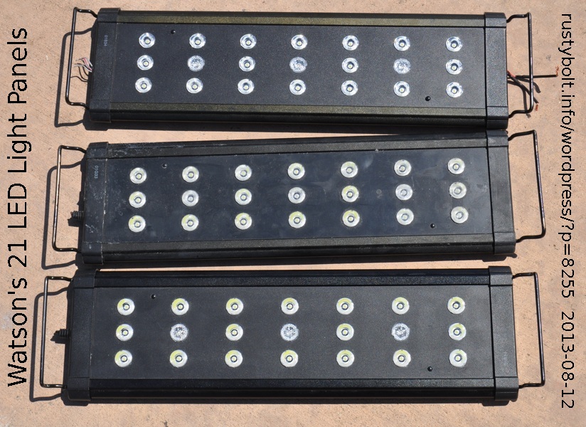
 I went to my computer club meeting this Sunday and they had a really good deal on the consignment table that I just couldn’t pass up: three 21 LED panels for five bucks apiece. They’re built very sturdy, with a body of extruded aluminum and screws holding the end covers in place. The ‘handles’ on the ends slide out to adjust to different widths, and the logo says Marineland, which leads me to believe that they might have been used for aquarium lights. Gee, how about that? I guessed right. I did a Google search and guess what I found!
The cables have been cut off, but I took one end cover off and I can access the wiring inside and splice a new cable on to it and put some heat shrink sleeve on the joint, and then put the end panel back on and no one will know the diff. One guy said he used one with a 12V adapter, so apparently the panels run on 12VDC. I just wish I had more info. One panel has a display and push buttons on the end, so I think it has a microcontroller and dimmer circuit inside (I looked inside when I had the end cover off and the PC board has a few chips). I think that they were all joined together and one panel was the master. In any case, I have a whole lot of spare LEDs, most likely 1 watt, with the lenses to go with them, if I want to cannibalize one of the panels. Cool!
Update Aug 19
I removed the end caps and found that if I pulled out the two plastic ‘bumps’ or studs, and then if I removed all of the lenses, I could slide the front plastic panel out and work on the circuit boards freely.
I traced the circuits out on the big LED circuit board and found out the following information.
All of the components are surface mount.
The LED board is made up of seven identical circuits, each with three LEDs in series. There are six white LED circuits and one blue LED circuit.
The uppermost of the three LEDs has its anode connected to positive. The cathode of the bottom LED is connected to the collector of a “D882” power transistor.
The emitter of this transistor is connected to two very low value resistors connected in series. These resistors are “R620” or 0.62 ohm, and “1R2” or 1.2 ohms. The other end of the resistors is connected to negative.
The emitter of this D882 transistor is connected to the base of a smaller transistor. The emitter of the smaller transistor is connected to negative. The collector of the smaller transistor is connected to the base of the D882, and both of these are connected to a “362” or 3600 ohm resistor. The other end of this resistor is connected to positive.
The current to turn on the D882 comes from positive through the 3600 ohm resistor. When the amplified current through the D882 and through the two low value resistors gets up to 0.35 Amp, the voltage drop across these low value resistors rises to 0.63V. This voltage is also across the base to emitter of the smaller transistor and it turns on, and shunts away the current from the base of the D882. This turns off the D882 and no more current can pass through it. In effect, this limits the LED current to 0.35 amps. That is about the maximum current for a 1 watt LED.
The circuit board is screwed down to the aluminum body which acts as a heat sink. There is a large amount of white heatsink goop between the board and the body, so if you take all the screws loose, you will a very messy white circuit board and body that will get all over everything. It is best to leave the board screwed to the body.


