default

2013-11-28 Another Million Dollar Idea – TV-B-Gon

The makershed.com website sells the TV-B-Gon, which apparently is a microcontroller that emulates many remote controls by putting out the many IR codes for turning a TV off.  I could take it into a restaurant and turn off the nearby TV so that we can eat without having to scream at each other.  This is a great idea, if you can get away with it, and not have someone discover how you are doing it.

I thought about it and came up with a plausible way of hiding it.  I would try to get the circuit board to be as slim as possible, less than 8 millimeters, but it can be long, 50 to 100 mm or more. The actual size of the board would be determined by the following item.

I would try to obtain a replica of Harry Potter’s wizard’s wand.  If I could not, then I might try to make one out of a thick twig from a tree, or a piece of wood such as a dowel.  Then I would hollow out the dowel on one end, deep enough to hold the circuit board and some button cells.  I would also put a reed switch inside as the of/off switch.  I would have to use a magnetic ring to turn it on.

I have thought about the use of button cells, and how well they would work and how long they would last.  IR LEDs take a lot of current, so the button cells might not be able to supply enough current.   I think a good solution is to connect 1 or more 1 Farad supercapacitors across the button cells.  As the current exceeds the cells’ capabilities, the 1 F caps would discharge and supply the high peak current needed to keep the circuit running.  Then when it’s off, the button cells would charge up the 1 F caps and it would be ready to go again.

I went online and checked the prices of replica Wizard wands.  The ones I saw were in the price range or $30 to $50, and were deemed to be replicas of Harry Potter characters.  I really don’t need to have a real replica, I just need it to look like a real wizard’s wand.  I may try to find a picture of a wand, and go from there and make my own.

While  I was searching I came across this wand.  It’s a Kymera remote control wand, with thirteen gestures.  It can learn 13 different controls by pointing it at a remote control.  It sells for $75 on Amazon.  I really didn’t want to spend that much, and besides I don’t think it could learn the sequence from the TV-B-Gon.

I found a wand that lights up and makes noise for $4.88, which is very inexpensive and it probably has a place for batteries and a LED and circuit board.  At that low price, I think I’m going to buy two so I can tear one apart and find out how it’s made and see if I can change it to something like the TV-B-Gon.  Then I found another one that looks the same, and it’s only $2.95.   I may try one of each.

default

2013-11-27 Blue Bottle And Xmas Tree Light Experiment

While walking to the park, I found an empty deep blue bottle lying in the grass.  The label said Bud Light Platinum, and was most likely filled with it, but the extra cost was for the deep blue bottle and clear plastic label.  I took it back home and peeled the label off.  This evening I looked through it at a string of Xmas tree lights with red, amber, green and blue LEDs in it.  What I saw was not surprising, but interesting.

I could see the blue and green LEDs okay, but the amber and red LEDs were barely visible.  The dark blue glass is acting as a narrow band filter, allowing only the colors that are close, such as blue and green, to get through.  The longer wavelengths of red and amber are filtered out.

default

2013-11-26 Button Cell Runs Flasher For 26 Days

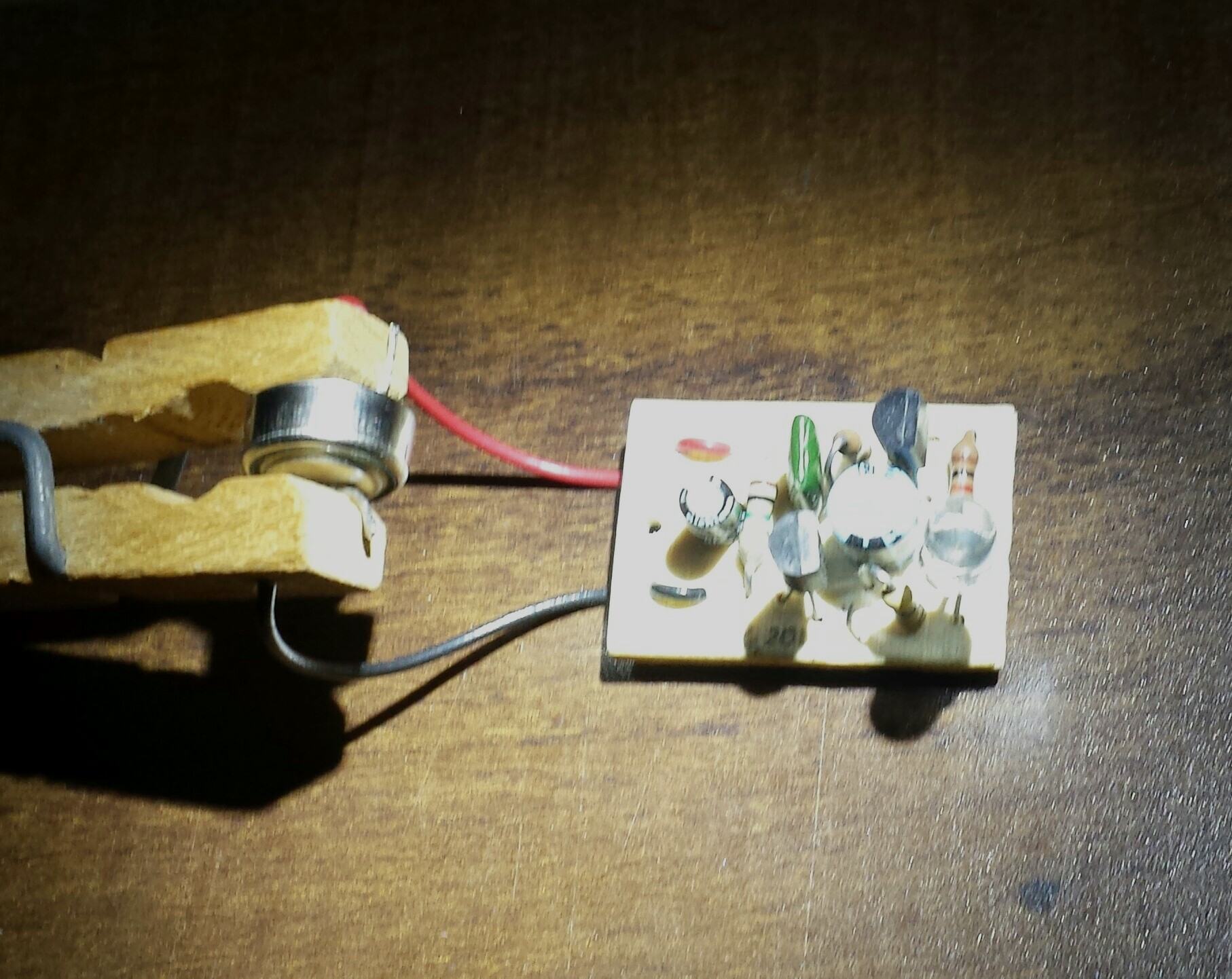
IMG_20131126_203656Last month, on Oct 23, I connected a fresh LR44 button cell up to one of my two transistor flashers.  It ran up until Nov 18 for a total of 26 days.  That’s about 624 hours.  Assuming that the LR44 has about 150 maH capacity, then the flasher is drawing about a quarter of a milliamp.  But I can’t say for certain what the average current is because as the cell voltage drops, the current also decreases.  It may start out higher than 1/4 mA and end at less than 1/4 mA.

I used a clothespin for the clamp to hold the wires to the button cell.  I drilled small holes through the wooden ends, and stripped the wire, put it through the hole and bent it over so it made contact with the cell.  Previously I used screws and nuts, but this does an adequate job and is a lot simpler.  You could use any plastic clip with enough width between its jaws to hold the cell and wires.  It just has to be an insulator, such as wood or plastic.  A paper clip could be used it it is wrapped with some tape to prevent the metallic wires from shorting the cell.

default

2013-11-22 LEDs Power JT FLasher – Continued Experimenting

I added a 1 Farad capacitor to the Xee2 flasher circuit I blogged.  I left the 10000 microfarad capacitor connected, but this is only 1 percent of the 1 Farad capacitor so it really doesn’t make any difference.  I used my LED task light to illuminate the 4 LEDs and charge the capacitors.  I connected it up in the morning, and left it running for several hours.  I came back a few hours later and the LED was flashing, and the flash rate was about 1.5 per second.  I noticed that as the input voltage increased, the flash rate also increased.

The voltage across the capacitor had risen to about 1.28 volts, and seemed to have leveled off, as if the amount of current drawn by the flasher was equal to the current from the charging LEDs.  I thought the flash rate was a little bit too fast, so I added another resistor to the 680k total, bringing the total up to 1 Megohm.  The flash rate slowed down a bit, but the charging current was now more than the flasher current so the voltage across the 1 Farad capacitor started to rise again.

Later in the evening I checked the voltage and it had risen to 1.58 volts, which is almost as high as the maximum voltage that I measured on the 10000 microfarad cap.  This indicates to me that the flasher current is slightly less than the charging current, and the circuit should fully charge in bright sunlight.  I then turned off the task light, and left the circuit flashing overnight.  I woke up this morning after about 8 hours and the voltage had dropped to 1.225 volts, and the LED was still blinking, like it should be.  This means that the 1 Farad capacitor is large enough to sustain the flasher for most of the night.

But one thing I haven’t tried is to charge the capacitor with direct sunlight.  I have been using the task light mainly because it’s cool and overcast outside and because I can charge it when it’s dark.  But I have thought about a few possible problems.  The LEDs have a lens that should focus the sunlight on the LED chip when it’s pointed at the sun, but what happens when the LED is held fixed, and the sun moves across the sky?  Will it get charged for only a short time when the sun is focused directly on the chip?  Even so, will this and the remaining charge time be enough to fully charge the capacitor?  I won’t know until I try it out outside.

One possible solution would be to arrange the LEDs so they each point to the sun at a different time of day.  They would point in an arc from east to west.  As the sun moves across the sky, each would get maximum sunlight at a different time of day.  But will this be enough current to fully charge the capacitor?

In the past I have modified the LED lens by sanding it down flat and then polishing it with very fine sandpaper and finally toothpaste to get the lens to be clear.  This spreads the light out, and would allow the sunlight to hit the chip from a much wider area.  I can do that with these LEDs, but I don’t see this as being practical when I need to do four LEDs per flasher times two dozen flashers – that’s nearly a hundred LEDs.

Another solution would be to add more LEDs.  Red LEDs are inexpensive, probably about ten cents apiece.  But if I have to use more than 6 or 7 of them, it would probably be better to buy a 2 volts solar cell for $1.15 (USD) from Futurlec.com.  One or two of these could probably charge several 1 F capacitors, and supply enough current to run several flasher circuits.  But then I would have to run a pair of wires between the flashers, and this Xmas tree light wiring mess is what I was trying to avoid.  I would rather have each flasher completely independent from the others.

There is another thing that I need to do.  The current from the LEDs may be enough to allow the flasher to use more current.  At this time I have a 1 Megohm resistance and a 1 uF capacitor, which gives a flash rate that looks okay.  But I may want to reduce the resistance and increase the capacitance so that each flash uses more power and is brighter.  It’s a matter of getting a balance between how much current the LEDs can supply in bright sunlight and how much current the flasher can use during darkness and still flash for about 6 to 8 hours.

Sunday Nov 24 – Since it was sunny, I decided to put the four LEDs outside.  I mounted them high enough to get hit by the sun all day long, and ran a pair of wires from it, through the wall, and inside where I can monitor it without going outside.  By the afternoon the 1 F capacitor had charged to only 1.025 volts.  I think the problem is the LEDs get direct sunlight only a fraction of the day, and the rest of the day the sun doesn’t hit the chips directly, and they put out very little current.

Update Nov 28 – The day was sunny, so I went out and pointed the four LEDs directly toward the sun for a few minutes.  I tried to get the shadow below the LEDs to be right below them, hoping this would align the lens and the chip.  Later, at dusk, I measured the voltage across the 1 F capacitor and it read 1.238 volts.  This was higher than past days, but I can’t say whether it was because of the time I aligned the LEDs or if it was because it was a sunny day.

In the past few days, I have watched the LED blinking late at night, and the voltage was then only about 1.025 volts, so I would say that the four LEDs are capable of doing an adequate job of charging the 1 F capacitor if the sun hits them long enough.

One idea I came up with was to use the plated disk from a bad hard disk drive.  These have a mirror finish, and would make a good mirror to concentrate the light on the LEDs.  The trick seems to be getting the disk or disks mounted so that it or they direct the light properly to the LEDs.

default

2013-11-20 LEDs Power TE Flasher, Not JT Flasher

My recent two blogs on powering a flasher with four red LEDs used a flasher made by modifying a Joule Thief.  It works fine, but it requires a toroid core and wire; the flasher I blogged earlier does not require any inductor.  It is a switched capacitor or charge pump,. and it works okay with two transistors.  It also has a daylight sensor that shuts it off during daylight hours.

What I have to do is put it on a Farad capacitor, charge the cap up to 1.5V, and see how long it will flash.  I’m aiming for 7 or 8 hours, so it will get through to midnight during the winter months when days are short.

default

2013-11-13 Choke Burns Out When Batteries Are Changed

A lady at work brought in a solar garden light for me to look at.  The problem was that it wasn’t working.  It consisted of a string of LEDs, all colored orange, just like a Xmas tree light string.  On the end was a small box that fit in the palm of my hand.  The top of the box was covered by a solar PV cell, and the bottom had a battery compartment cover which clipped onto the spike that held it to the ground.  Under the battery cover were originally two AA cells, both NiCd rechargeables.

The garden light quit working and the lady removed the defective batteries, which were the reason that it had stopped working, and replaced them with new batteries.  This was the correct solution, and would have worked if she had chosen rechargeable batteries.  But instead she used regular AA cells, which were 1.5 volts each instead of 1.25 volts for rechargeables.  The increase from 2.5V to 3V caused excessive current which burned out the  47 uH choke.

I removed the batteries and opened up the snap-together case, removed the screws holding the circuit board, and examined the parts and saw nothing wrong.  The circuit board held just a few parts: the light green colored 47 uH choke, an unmarked IC that looked like a transistor except it had four pins, a 9013 transistor, an On/Off switch and a few other parts.  Since I didn’t know anything about the four pin IC, there was no way this could be fixed if it was bad.  So I used the cheapo DMM to check the choke for continuity.  A choke of this value should measure from a few ohms down to a fraction of an ohm.  Instead, it measured infinite resistance, or open.

Ah-HAH!  I had found at least one of the problems.  I unsoldered it and looked for a replacement.  It had to be small because the circuit board was mounted on two posts with the components facing toward the case, and there was limited room for the part.  I could not find a small choke of that value, so I got a T231212T toroid core from Surplus Sales out of a bag.  I wound it with a few inches of enameled wire and measured the value, and it was 52 uH, which was close enough.  I think the core had 6 turns on it.  I soldered it in and crossed my fingers.

I inserted two AA rechargeable cells and turned the switch on.  Well, I was pleasantly surprised when the LED lights lit up.  So I reassembled the case and brought it to work.

default

2013-11-12 LED Powers Joule Thief Flasher – More Info

In my earlier blog, yesterday I discussed using a 1 Farad capacitor to hold enough charge to run the flasher for several hours, from dusk to midnight or later.  I checked Mouser’s parts and found a 1F 2.5V capacitor from Bussman for about 2 dollars in single unit quantities.  Kind of expensive but cheaper in the long run that replacing AA cells.  I will have to check some surplus websites and see if I can get some 1 F caps for cheaper.

I found new 1F, 2.5V capacitors for $0.65 each from All Electronics, so I bought some.  These are not low ESR capacitors, so they are not made for quick charging and discharging.  But with the flasher, the charging and discharging rates are very low, like only 1 mA or less.  So they should work okay without a problem.

I have a bag of several dozen red high brightness LEDs in my parts drawer, so I don’t need to buy any LEDs.  I may have to use more than four LEDs per capacitor because with four, the charging current may be too low to completely charge the cap before the end of the day.  I think with four, the charging rate will be slower than the flasher discharge rate.  But that’s okay because the flasher only has to flash from dusk until midnight, which would be at most 6 or 7 hours during winter at this latitude here in Southern Calif.  The front of my house faces directly south, so it gets maximum sun exposure the whole year, and the flashers should have no problems charging up full on a sunny day, due to the absence of shadows.   If I’m lucky, the 1 F capacitors may not discharge fully during the night, and when there is a cloudy day they may charge up enough to flash during enough of the night.

default

2013-11-11 LED As Solar Cell Powers Joule Thief Flasher

I’ve seen a lot of Xee2’s xee2vids on Youtube, but I don’t remember seeing this one before.  It’s dated Sept 2011, so it’s more than 2 years old.  The Joule Thief flasher obtains its power from four red LEDs connected in parallel, which are used as solar cells and charge a 10 thousand uF capacitor.  There is a ‘RK44’ diode between the LEDs and the capacitor, presumably to prevent current from discharging back through the LEDs AKA solar cells.  But I don’t believe it’s necessary.  The surface area of the LEDs, which I’d estimate to be a millimeter on the side, or one square millimeter, is one millionth of a solar cell that is one meter square.  Consequently the leakage would be one millionth of that of a large solar panel, and any leakage should be unmeasurable.  In any case, I’ve never known a LED to conduct measurable current in the reverse direction.  I don’t know what a RK44 diode is, but by eliminating it we save a half volt or more of voltage drop.

But then I thought why put the four LEDs in parallel?  Instead, put them in series and add the voltages up, to get four or more volts and that will allow us to change the circuit to a common two transistor flasher.  Yeah, I know: I’m taking away all the fun with the Joule Thief.  But it has about 50% losses in the coil and circuit, and eliminating the coil will save power.  It may be possible to run two or maybe more 2 transistor flashers from the LEDs.  But I digress, so back to the Joule Thief.

The 200 k resistor determines the flash rate along with the 3.3 uF capacitor. This also determines the current drawn by the capacitor, and the LEDs can only put out a very small curent.  So if the flasher draws too much current and flashes intermittently, then it may be necessary to increase the 200k, and to get the flash back to its intended speed, reduce the 3.3 uF capacitor.

Note that the 3.3 uF capacitor has no polarity, there is no plus sign.  This means that it should be non-polarized.  But if a polarized electrolytic is used, it looks to me like the plus side would be at the bottom, which is connected to negative through the coil.  However the capacitor may charge up in the opposite direction, so it would be wise to check the voltage across it to determine the correct polarity.  Or else use a non-polarized cap as shown.  If the resistor is high enough, the capacitor could be as low as 1 uF, which is available as a non-polarized type.

I have blogged my Supercharged Joule Thief Flasher, which presumably is more efficient than a conventional JT flasher.  But to be honest, it is very difficult to measure the average battery current of any flasher, because the flasher pulls a pulse of high current from the battery, then waits  a long time before pulling the next high current pulse.  In order to average out the current, it requires a very large capacitor to filter out the current pulses, and get a stable average current.  A digital ammeter will have the digits jumping around and it’s only a guesstimate of the actual average current.  But flashers use only a very small current, so the battery lasts a long time.  Most people would not be very concerned if the battery in a conventional JT flasher lasted only four months, and a supercharged JT flasher 7 or 8 months.  Either one seems to be a long time.

I soldered up one of these on the bench this weekend.  It works, but I have to get it right next to my 3 watt LED task light to charge up the capacitor.  The main difference between this one and the one in Xee2’s schematic is that I didn’t use the RK44 diode.  I also used the BC338 transistor, which is higher gain I believe  than a MPSA06.  Instead of 3.3 uF I used a 1 uF plastic capacitor.  In order to keep the flash rate low, I had to increase the value of the resistor from 200k to 680k.  As it is, the circuit works okay, but it draws enough current from the 10000 uF capacitor that when the LEDs are not charging it, the voltage drops over a few tens of seconds and the LED stops flashing.  Discharging is to be expected, but the discharge speed seems higher than I would expect.  One reason may be that the LEDs are letting current flow backwards, but I thought that this would be minimal.

Update Nov 18 – I got the stopwatch and made some measurements.  The flash rate was about 2 per second.  The inital voltage was 1.6V, and when I turned off the light, the 10000 uF capacitor took two minutes and fifty seconds to discharge to 1.4V.  I think the cap had been sitting around for awhile and needed to have a charge or two put on it to ‘reform’ its oxide layer.  Electrolytics may have a bit of leakage when they’re first charged up due to the oxide layer unforming during storage.  But after awhile they reform and the leakage goes down to what is normal.  All electrolytics have some slight leakage.  The larger the capacitor, the greater the leakage, and  10 thousand microfarads is a very large capacitor, so leakage should be expected (I didn’t think about it earlier – my bad).  So it now seems that the leakage backwards through the LED wasn’t a problem at all, it was the capacitor.

There are two things that I thought about after building this.  First off, I don’t need solar cells to make my Xmas flashing house decorations run off free energy.  They are now running from a single AA or AAA cell, which powers them for months, but the batteries eventually need  replacing and they always leak and corrode all of the wiring that touches them.  Replacing the battery with a capacitor and several LEDs is a great way to eliminate those problems.  One thing has to be considered: the running time.  I’m guessing that the 10000 uF capacitor, which is actually 0.01 F, is only going to run for 10 or 20 minutes before it’s discharged.  So it’s going to take more than a dozen of them to get the flasher to run after dark until midnight or later.  That’s too many to put onto a small flasher.  I will have to obtain some 1 farad capacitors, and since they’re only 2.5V, the LEDs still will not overcharge them at 1.6V.


default

2013-11-10 Holder for Camera (Cell Phone)

IMG_20131111_184528S1-CameraHolderA few weeks ago I made this camera holder for my Samsung Galaxy S4 out of a piece of 1 inch aluminum angle bar.  The part in the photo that is attached onto the tripod with the C clamp is the holder. I’m using a C clamp to hold it on because I have not yet drilled a hole in the holder and added a 1/4 inch nut to fasten it to the tripod foot.

I have a Body Glove rubber protective case on the S4, and it slides right into the holder snugly and will not come out unless I give it a good pull.  I have been using it for a few weeks and it comes in so handy that I had to blog it.  When I want to take a hands free snapshot or a movie, it’s the only way to go.  It’s just like a third hand.  The original reason I just had to make it was because I wanted to do time lapse movies, and holding a cell phone absolutely still for even just a few minutes is nearly impossible and my arm gets tired and I have to give up.  Time lapse videos are great, they can show a car trip of a half hour in just a minute or less.  But the camera has to be held still during the shoot.  And that’s too much for a person to do with his hands.

Also, the holder allows the camera to be mounted on a person or bicycle, like a GoPro video camera.  With this holder mounted to a hat or helmet, I could get some fantastic videos.  I can now mount the holder onto a remote control copter and fly it overhead.  There seems to be no end to the places to go and things to do when the camera can be held and positioned optimally.

Someone should sell these, but make them out of tough plastic so they’ll last for awhile.  Also add some adjustments so that one holder could fit many different sized cell phones.  Someone could make a lot of money with a successful design.

default

2013-11-08 Flash! Banana Erupts In Flames!

I was in for a very big surprise today when I pulled a banana out of the fridge and put it into the microwave for fifteen seconds to take the chill out of it.  I pressed 15 and the start button and watched.  About the 14th or 15th second this large fireball erupted from the end of the banana and went BZZZZZZT!  It scared the hell out of me!  I pulled the door open to stop the microwave oven, and pulled the smoldering banana out of the oven.  I looked at the stem end, and found out what had happened.  It got really hot really fast, and literally caught on fire, but then the steam inside of the stem spurted out and blew a jet of smoke out of the end.  The microwaves turned the smoke into an arcing ball of flame!  The end if the banana was still smoldering embers as I looked at it.

The lesson I learned is if I want to prevent this from happening again, I should cut the stem off of the end of the banana before I put it in the Microwave oven.  But then, just maybe, I might try to do it again. (sly smile!)

© RustyBolt.Info/wordpress
CyberChimps