


 This LED light is identical to the others with white LEDs, but I used red, green and blue LEDs for a Christmasy effect. The schematic of the circuit is on a post-it inside of the lid.

2012-07-23 RGB LED Light


2012-07-22 MOSFET Phase Shift Oscillator
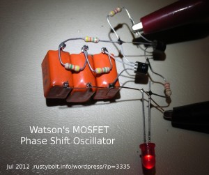 I tack soldered this phase shift oscillator together and used a 2N7000 MOSFET for the PSO. The second transistor in the upper right is a 2N4401 being used as an emitter follower to drive the LED. The LED would draw too much current and load down the oscillator – the PSO has to have a voltage gain of at least 29 to oscillate.
The three orange capacitors are 1 uF each. The 4.3 megohm resistors connect them to the drain and gate. The 4.7k resistor is the drain load resistor. The remaining 220 ohm resistor is to limit the current through the LED. The circuit oscillates subsonically, less than 1 Hz. This is dependent on the 4.3 meg resistors and 1 uF capacitors. The 2N7000 gate draws no current so the resistors can be very high without disturbing the bias. The supply voltage is about 5 volts.
2012-07-21 Ring Oscillator
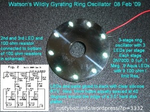 This is a pic of the ring oscillator I built in Feb 2009. It’s the same as my earlier blog, but it has three LEDs per stage, so the supply voltage has to be higher.
I’m going to try to upload the few second video. This was taken from the back because the LEDs were too bright for the camera.CIMG1623 Will the upload work? I had to click on the link more than once to get it to download the video, but it worked.
2012-07-20 Homemade Components
Bespoke – The experimenter sometimes may have a difficult time obtaining parts. In a pinch, he may be able to make his own parts. This generally applies to passive components such as capacitors, inductors, resistor, but on occasion may extend to active components too.
Coils – Most of use who have built Joule Thiefs are familiar with homemade components. Yeah, we start with a bare toroid core and some wire, and wind our own coil. Or should I just call it hand-wound? I didn’t make the wire or core. But I’ve made JT coils out if 16 feet (5 meters) of telephone wire, wound on a AA cell, which is then removed and the ‘donut’ of wire is tied or taped to hold it together. The core is an air core.
I’ve read about how the old timers made their own crystal radio sets. They used an empty Quaker Oatmeal box for the coil form, and wound thin insulated wire on it. They then made their own capacitor by putting sheets of aluminum foil between the pages of a book. Varying the weight on the book changed the capacitance. And the detector, too, can be made from a small piece of galena crystal (more about this below). Except for the headset, this makes the crystal radio set the most homemade of any electronics project.
Capacitors – The Tesla Coilers need high voltage capacitors for their TC, and that can be very expensive. Some coilers make their own salt water capacitors from beer or beverage bottles, aluminum foil and a tub of water with salt. And of course, their coil is homemade – or hand wound. Google for Tesla Coil and you’ll get tons of hits.
I’ve made a ‘gimmick’ capacitor for my FM wireless microphone. I needed a 4.7 pF capacitor between the emitter and collector of the oscillator, and low values in the few picofarads are uncommon. I took two 2 inch (100mm) lengths of 24 AWG (.5mm) solid insulated telephone wire and twisted them together tightly. The result is a capacitor that’s about 1.5 to 2 pF. Two or three of these in parallel made a 4 pF capacitor. These also work for tuning the tank circuit in the collector. Of course the tuned tank coil, too, is made by hand.
Resistors – I’ve done the experiment where the experimenter draws a line on a piece of paper with a pencil, then measures the line’s resistance. The graphite in the pencil is the carbon resistance element.
Old timers had resistors that were considerably bigger than the tiny 1/4 watt ones we have today, which are a thin film of carbon on a ceramic substrate. Those old ones had a body that was solid carbon, much easier to work with. Back then they often found that they needed a resistor that was higher than what they had. Their solution was to file a groove in the side of the resistor. This reduced the cross section of the body, so less carbon meant more resistance.
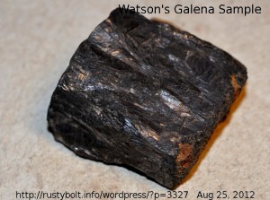 I’d like to explain the galena crystal in the crystal radio. Today, a silicon diode costs only a few pennies and will work for a detector, but it takes a higher voltage signal to conduct compared to a germanium diode. The germanium diodes are no longer available, so about the only alternative is a high frequency Schottky barrier diode, which are uncommon and hard to obtain. Some crystal radio fans like to use the galena crystal, not only because it conforms to the original crystal radio, but they like to be able to adjust the cats whisker until they find a ‘sweet spot’ where the signal is loudest.
The galena crystal is not the only homemade detector. The old timers used to use a razor blade, with a cat’s whisker contacting the blueing on the blade, which had rectifying properties. They called these foxhole radios, because the soldiers had to make do with the limited resources available.
2012-07-19 Surge Protectors – Just Say NO
Surge Protectors – Pros and Cons
I was just sitting there, working on something, when I heard a loud BZZZT and immediately I smelled smoke. I couldn’t tell where the burning smell was coming from. I became concerned to the point of panic that there would be a fire breaking out any second. I couldn’t see any smoke, but after several minutes of sniffing, I managed to track down the source of the smell. It was a surge protector under the desk, and I immediately unplugged it and took it apart. There in pieces inside, all burnt and blackened, was the MOV (metal oxide varistor), which is the part that is supposed to protect against surges. It had failed catastrophically, and burned and blackened the inside of the power strip. Fortunately the power strip case was made out of metal, not cheap plastic like most power strips are made nowadays. I think that if it had been plastic, it might have caught on fire.
This is not the first surge protector that I’ve seen burn up by itself, with no reason other than it just failed on its own. I opened up another power strip that had also burned up, and in that case, no one was around at the time. Fortunately it didn’t catch on fire. One lesson to be learned from this is to always buy a surge protector that has a case made of metal, so it won’t catch on fire. This will probably add considerably to the cost, but after I tell you the rest of the story, you may change your mind.
Surge protectors have been around since the early days of the telephone, over a hundred years. Only in the last few decades have they been widely introduced in power strips. If you go to the store such as Radio Shack or Best Buy, you may see a regular power strip for less than ten dollars (U,S,), but you look at the surge protector power strips and they’re $19.95 or more, on up to over a hundred dollars. Think about this: the two or three MOVs that they add to a regular power strip cost less than a dollar, and the difference in labor to add them is probably even less. Then why do they charge so much for the surge protector? It’s because the sales droids convince the uneducated customer that their TV, stereo, PC or whatever will burn out if they don’t buy a surge protector. Manufacturers do not recommend that their equipment must be connected to a surge protector. The stores sell TVs, etc., at razor thin profit margin, and then they make back millions of dollars selling the accessories such as surge protectors, batteries and USB cables at a thousand percent markup. Just say NO to crook stores and sales persons.
If you look at the surge protector package, you might read some rating number that’s in the thousands of Joules. This number is supposed to give some information to the consumer about how well the surge protector is supposed to protect. I shall tell you how the surge protector is supposed to work. Have you noticed how I have been using the phrase ‘supposed to work’ instead of ‘works’? I’ll explain this as I go on.
The surge protector has the MOV connected across the wires. Each MOV is about the size of a nickel. This device is supposed to act like a short when the voltage gets too high, and let the surge pass through itself, while absorbing the Joules of energy in the surge. Well, it’s only the size of a nickel, and if the surge is too powerful, then the MOV will fail, and could burn up with the same smoke and results that I described above. When this happens, the MOV does not protect any more. It has died, and your surge protector is now worthless, but it still functions as a power strip. If the surge happened when you were not around (most likely it did), then you don’t know that the surge protector is worthless.
By the way, I should add that the surge protector does nothing to protect against sags or brownouts, which can damage your equipment, too.
But how big are the surges? Will they always be less than that number they gave you on the package? Probably not; they will most likely far exceed that. Most of the electrical damage is cause by very powerful surges caused by lightning during a thunderstorm. These need to be eliminated by a surge protector that is built into the power lines where they come into the building. That location has a good ground to allow the surge to travel into the earth. When the surge protector was introduced to the telephone system, they were installed at the point where the telephone enters the building. This point is an important point to remember. That point has a good ground, connected to a stake driven into the ground or a metal cold water pipe.
Socket To Me – Most surge protectors are plugged into a socket that is dozens of feet from a good ground, and this causes the surge protector to become less effective. In fact, some houses used to have two pronged outlets, and the outlets were removed and replaced with three pronged grounded outlets, and they then have a poor or nonexistent ground. You have an expensive surge protector that can’t do its job because of the adverse conditions that it is in. And the good ground connection is the most important part of surge protection. I saw a house where the electric meter and breaker panel at the main entrance used a cold water pipe for the ground. But the old house had metal pipe that corroded and was replaced by plastic pipe. Now the house has either a poor ground or no ground.
One other important item. The manufacturers of TVs, PCs and other devices powered from the electric system have done testing on their products and in general they do not sell equipment that is vulnerable to surges. Take for instance the typical PC power supply. The power input to the power supply has extensive filtering to not just keep out surges, but to keep the interference generated inside the power supply from getting out into the rest of the electrical system. If you read the label on the equipment, you may see a rating such as “100 – 275 VAC”, which means that the TV or PC can handle more than double the standard voltage of 120 volts AC that is found in the U.S. If you put 275 volts AC on a surge protector, it will fail.
Read the Fine Print – I have read some of the fine print on the packages of surge protectors. Often they warranty that their surge protector will protect, and pay some sum to repair or replace the equipment that is damaged. What the fine print does is make the conditions so restrictive that it is doubtful that the consumer will be able to collect on the insurance. The important thing here is to read the fine print before you buy a surge protector, or suffer the consequences.
Other alternatives – The surge protector is just a minor method of protecting your equipment. There are other ways of protecting, such as a UPS, uninterruptible power supply. This UPS generates power when the electrical system goes dead.
Another way to protect is to route the electrical power through a transformer. These typically have filtering to reduce any incoming interference, spikes in the electric supply. But they do not protect against sags or brownouts. These other methods are of higher technology than a cheap surge protector, do a better job, and consequently they cost more.
Conclusion – This all boils down to my opinion: I am not an anti-surge strip fanatic, I’m just telling the truth: surge protectors are not what they are made out to be. I recommend you don’t buy a surge protector power strip. Use a regular power strip instead. If you must buy one, never, ever buy it from a retail store.
Update Aug 25 – My ex co-worker asked me “So what does one do? Unplug the TV?”
If you’re going to unplug anything, unplug the surge protector. Assuming that you have the TV plugged into it. That way, the TV and the surge protector won’t burn up if there’s a surge.
I know what I am doing. I learned from the School of Hard Knocks – Experience. I don’t use a surge protector because of the fire hazard, and if the TV or anything else goes out on account of a surge, I’ll just replace it (or more likely repair it if I can get the parts. Most likely the fuse on the circuit board is blown and it will cost less than a dollar for the fuse. At least there will be no surge protector to catch fire and burn down the house.
The other choice I would make is to have an electrician install a surge protector at the main breaker panel where it can be properly grounded. This can cost hundreds or even more than a thousand dollars. That’s why most people think it’s better to buy a surge protector power strip. Better, at least in the short term, for their wallet. Just make sure they read the fine print on the surge protector’s warranty. And make sure their homeowners insurance is paid up.
2012-07-18 Closeup Photo of Germanium Diode
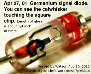 I took this pic a while ago, May, 2001. The germanium chip and catwhisker are so clear and visible. The GI stands for General Instrument company, the maker. I know that silicon chips are light sensitive. If germanium chips are, then this one should make a good light detector.
2012-07-17 Using a MOT In A Joule Thief
I have been noticing that several of my Google Alerts have been about using a MOT (microwave oven transformer) in a Joule Thief. These have mostly been Youtube videos of experimenters that have built a JT using a MOT for the coil.
There are a few disadvantages here. First off, the MOT is huge, heavy and for a JT it is a serious overkill. The MOT can handle more than a thousand watts, and the JT needs much less than a single watt. I think a better choice would be to use a 6.3 volt AC, 1 amp filament transformer, which is still overkill but much less than a MOT: it will fit in the palm of your hand without breaking your arm(!)
Another disadvantage brought up in one of the videos is the MOT will give you a nasty shock. The solution given was to put a neon lamp across the high voltage winding, which lights up brightly when the JT pulses it with current.
Then there is the scarcity of MOTs. You can’t find these at your local Radio Scrap store. You have to cannibalize a microwave oven to get one. Why not just do it right and buy a 6.3 volt, 1 amp filament transformer?
In one video he used a neon sign transformer (NST) insted of a MOT. He wound several turns around the core and connected the ends to a speaker. Every time the JT triggered, a click sound would come from the speaker. He showed the brightly lit neon lamp he put across the high voltage winding, which was used to drive the base. The JT could run at a speed that was as low as one click a second.
One important point about the MOT. This is NOT a toy. You can get severely shocked by the high voltage it can produce. Also, it’s easy to take a toroid of say 1 to 1.5 inches and wind a lot of turns on it, and make a coil with the high ratio of turns that will act the same as the MOT. The (ICH) ZJ43615TC from Surplus Sales might be an acceptable choice.
I’ll probably be back with more exciting stories as the JT with MOT adventures continue.
2012-07-16 Reversed Joule Thief
This .PDF document is on a Yahoo group called Radiant Energy. You may have to log on to view it. It is not a true Joule Thief because it does not conform to the conventional JT that has a single transistor with a coil that has two windings. People just can’t seem to get the terminology correct, they should call it a voltage boost converter. But the catchy JT name seems to have grabbed people’s fancy and they use it for just about any circuit that lights a LED. Which reminds me: the true conventional JT was meant to light a LED, so any circuit that does not have a LED is technically not a JT.
http://f1.grp.yahoofs.com/v1/YB4EUGOgIx9S_q0rDYU6zAjh4TZ3TMYAaoEJgVGOxjp-Nwv2Wkg6iXBYn6V8E8RGYQIcjtzK_IgZ1Rx8FHmPYD5v42yVn1sp/Misc.%20Schematic%20%26%20Construction%20Contributions/Reverse%20Joule%20Thief.pdf
2012-07-15 Joule Thief – Vce(sat) Is Important
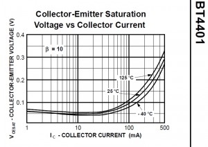
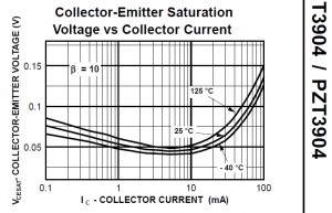 Peter asked me why the Joule Thief transistor’s Vce(sat) is important. I will try to make an analogy of the current in a transistor to the flow of water in a pipe. In a JT, the transistor is supposed to be like a switch: it’s on (like a short) or off (like an open). But the current flow through the transistor is like the flow of water through a pipe. If the pipe is large diameter, then the flow is not restricted. But if the pipe is small, then the flow is restricted, and there is a difference of pressure (voltage) between the top end of the pipe (the transistor’s collector) and the bottom end of the pipe (the transistor’s emitter).
The Vce(sat) is the value, often found in a chart, that is given when you read the specifications in the transistor’s data sheet. It’s like an indication of the size of the pipe between the emitter and collector of the transistor. If the transistor is capable of handling 200 mA with a voltage drop of a quarter volt, then it has a smaller pipe that will have a higher voltage drop when it is turned on (saturated).
If you search for the 2N3904 datasheet from Fairchild (it’s a .PDF) and view the page with the graphs, you will see a graph (see the attached picture) named “Collector-Emitter Saturation Voltage vs Collector Current”. The graph has three lines: one for high temp, one for room temp, and one for cold temps. The only one we’re interested in is the room temp line. You will notice that this line has a saddle shape, with fast rise towards the right side. If the transistor was a resistor, the line would be a straight line, but it is not a resistor, it is a semiconductor, and has a non-linear voltage-current line.
Also notice that in the corner of the graph it says “β=10”. This means that the transistor is saturated, causing the beta to be forced to 10 . Some higher current gain transistors may use 20 or 30 but they are still saturated.
Notice that the graph ends at 100 mA on the right side, implying that the 2N3904 was not meant to be operated at more than 100 milliamps. However, in the absolute maximum ratings on the first page, it gives 200 mA as the absolute maximum current rating. A normal Joule Thief requires much more than 200 milliamps peak, and this exceeds the 2N3904’s absolute maximum ratings. But if you guesstimate the point off the right hand edge of the graph, the Vce(sat) will be greater than 1/4 volt when the current exceeds 200 mA. When the Vce(sat) is greater than 1/4 volt, the loss becomes excessive, and more power is wasted in the transistor and does not get to the LED. That is why I do not recommend using the 2N3904 for a JT. Instead use a PN2222, 2N4401 or BC337-25, which cost the same or less than the 2N3904 (see note below).
Back to the graph. What you want to see is a graph that shows the Vce(sat) less than 1/4 volt at a current above 200 mA, and preferably at currents above 500 milliamps. The transistors I gave above can meet this requirement. Check their specifications and/or graph, and you will see the difference. The other better transistors (for a JT) can handle much more than 1 amp. The 2SD965, 2SD5041, 2SC2500, SS8050, NTE11 can do this. You can see from the graph for the 2N4401 that it is capable of handling about 300 mA at 1/4 volt Vce(sat), which is much better than the 2N3904.
Note: Looking at the specifications for the 2N3904, we can see that it is meant to operate at a few tens of milliamps or less, and has low noise so it can be used as an amplifier. In order to get good high speed performance, the size of the 2N3904’s chip is kept small, so it doesn’t have the high current carrying capability of the PN2222, 2N4401 or BC337. Save your 2N3904s (and BC547s) for amplifiers and low current switches – they work great for this. Use the other transistors for the Joule Thief.
2012-07-11 joule Thief watson
I did a search on Google for Joule Thief watson and came up with a bunch of hits. I clicked on the Google IMAGES listing, and came up with a lot of my blog pictures interspersed with pictures from other websites. I can tell you that generally if it is one of my (Watson’s) pictures, it will be identified as such with text in the picture. If it does not have any text that IDs it as mine, then it is not my picture. But in any case, this search comes up with a lot of hits and images that are mine and from others. To search, you have to click on this link and then go to the second page for the images.
