default

2012-08-05 Third Winding on Joule Thief Drives LEDs

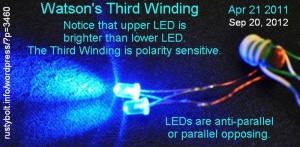
I posted this to my late, great wasts0nseblog but forgot to post it to my new rustybolt.info blog.  I wound a third or tertiary winding on a Joule Thief to drive another LED.  The LED could have been put in parallel with the existing LED IF it was the same color or the same forward voltage.  But it wasn’t the same color.  If you’ve ever experimentind with a JT, you might know that if you put a red LED for example, in parallel with the blue LED, the red LED will hog all the current and the blue LED will get none, just because the red LED’s forward voltage is so much lower than the blue LED.

So to get around this, I wound a third winding on the JT’s core, and it drives the other color LED.  If you notice, in the picture there are two blue LEDs and they are connected anti-parallel or cathode to anode.  One LED lights on one half of the AC cycle and the other LED lights on the other half of the cycle.  But one LED is brighter, and that means that the third winding’s connections are polarity sensitive.  It will make a lot of difference in the brightness if you connect the LED the wrong way.

The JT is power limited, so the available power will split between the original LED and the LED on the third winding.  The number of turns is not critical, as long as there are enough to get the voltage up to the forward voltage of the LED.

Back to experimenting…


default

2012-08-04 LED V Boost, 2 Cell

This was from June, 2003.  I still hadn’t tried to experiment with the single transistor Joule Thief circuit to get it to be powerful enough to drive 3 LEDs.  The circuit I used is found here.

default

2012-08-03 Candelabra Adapter Made From Junk CFL

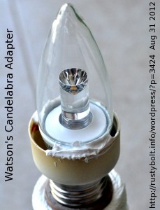
I needed a candelabra socket with a switch, like the ones that are available for the regular light socket.  But I couldn’t find one, so I improvised.  I took the base from a dead CFL and soldered the wires to the candelabra base of the LED light, then positioned it in the ‘adapter’ and glued it in with a bit of silicone seal.  The light and base should never get hot enough to damage the silicone seal, and now I can screw it into a regular light socket with the switch built-in.  The 2.5 watt LED light should draw very little current and I’ll be able to leave it on for longer without being concerned about wasting electricity.  And it’s a great way to get rid of those leftover CFL parts that we seem to accumulate.

Update Sep 20 – I ordered some adapters for two dollars U.S. apiece from an amazon seller, Econotone.Inc.  They’re called Satco 92-400 Medium to Candelabra Socket Reducer.  For two bucks each, I figure it’s not worth it to mess around with the CFL sockets, especially since once you glue the light bulb in, you can’t take it out and use it in a candelabra socket.

default

2012-08-02 Watson’s Audio Frequency Joule Thief

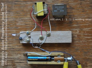
I have a lot of these 600 ohm telephone hybrid transformers that came out of a PBX (see here for much more info).  They’re sturdy and well built, and make great audio transformers.  Last week someone posted a video to Youtube of some Joule Thiefs that used an audio transformer and the frequency of oscillation was so low that it could be seen with the eye: just a few Hertz.  So I decided I should try to make a similar one that uses an audio transformer and runs at a low frequency.

Each winding starts on one side and ends on the other side of the transformer, directly across from the start.  The 5th pin is not connected and is for alignment purposes.  For the primary winding (white wires in the pic) I connected two of the 600 ohm windings in series for an impedance of 2400 ohms.  I used a single third winding (red wires) for the feedback winding.  Each winding has a resistance that is about 50 ohms, which is too high for an efficient Joule Thief, but it works.  I can see the detrimental result; the battery current is only 1/3 of a milliamp at 1.5 volts and the LED is dim.  The transistor is a 2N4401 and the resistor is 39k.  I tried other lower values of resistance, but the oscillations were intermittent and unstable.

Well, the frequency was very low, but not as low as the ones in the video.  At 1.5V the frequency was 144 Hz, too high to see visually, but very low for hearing on a small speaker.  The thought came fleeting through my mind that it might be possible to get the frequency lower by adding the fourth winding in series with the other two primary windings.  But I didn’t dwell on it because I could see that the two windings already had far too high a resistance to allow enough current to light the LED properly.  I think the better way to go would be to replace the transformer with one similar to the ones seen in the video.

Back to experimenting…

default

2012-08-01 Watson’s Modulated Light Beam

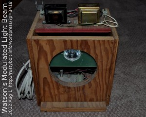
A long time ago, about 1966, I wanted to modulate a light beam with audio. The LEDs available at that time were indicator grade, not bright enough to go any distance. So I decided I would build a modulator and connect it to a powerful incandescent light. At first I used a burned out car headlamp with the glass cut out of the front and a 12V tail light lamp mounted at the focal point. Later I removed the big reflector and installed the 12V, 20W halogen reflector light that is seen in the picture.

The AC from the transformers on the top was rectified and filtered, and the 18 or so volts DC supplied the modulator, a power transistor. The light was connected as the power transistor’s collector load resistor. The audio fed the power transistor and amplitude modulated the light.

The receiver originally was a solar cell connected to an amplifier, but I found that the phototransistors I got from Radio Shack were good receivers. But the main problem with modulating a light bulb is that the bandwidth is very low because the filament has to heat and cool as it responds to the audio. The received audio sounds very muffled and it’s difficult to understand. But the high power light will transmit a much greater distance than the dim indicator grade LEDs at that time.

Today I could remove the Halogen bulb and replace it with a 1 watt, 3 watt, or 5 watt red LED and it could be modulated with frequencies much higher than audio, so I could use a carrier and frequency modulate the beam, making it much harder for snoopers to demodulate. I could also use a laser beam and get very narrow beam that would be difficult to intercept, but the atmosphere could have enough disturbance to interrupt the beam over a longer distance. A LED with a lens or reflector can give a much narrower and more powerful beam without the problem that the laser has.

Later I built a pair of full duplex transmitter/receivers using PLL chips to frequency modulate the beam, and I used 5 mm LEDs for the transmitters. I mounted them in a 4 inch plastic drain pipe with a glass lens at the front. They worked fairly well, but I got really tired really fast setting up one of the units a thousand feet away, then coming back to adjust the beam focus and direction, then going down to the far end to do the same thing, then.. etc., etc. Whew! I spent most of my time traveling!

default

2012-07-31 Joule Thief Beeper by Quantsuff

I got an email from QS saying that he posted a Joule Thief Beeper to his web page, about 2/3 of the way down.  I think it might make a metronome if the speed was adjustable.  basically it’s a two transistor circuit with a single coil made from the voice coil of an 8 ohm speaker.

I built one of these long ago, and used a 9V battery and small 2 inch speaker.  The circuit worked for a while, then failed.  The voice coil went open, possibly from excessive current, or else the voice coil vibrated itself to failure.  With a supply voltage of 1.5V, there should be no problem with excessive current.

default

2012-07-30 Joule Thief Comment

My comment  to a blog found here.

A very common way of boosting voltage does not use an inductor. Instead it uses a ‘charge pump’ or switched capacitor, or flying capacitor.

You can buy the Fair-Rite 2673002402 core for $0.12 (U.S.) apiece, and 12 turns of 24 AWG (0.5mm) insulated telephone wire can be scrounged from old scraps.  The BC337-25 makes an excellent JT transistor.

The efficiency of a conventional JT is around 40 to 60 percent.  Not all that good, but it’s simple and it does work.

default

2012-07-29 V Converter, 1.5V to 9V

I found a Youtube video with a two transistor circuit (some mistakenly call this a Joule Thief) that is used a a voltage booster to give 9V from 1.5V or 3V.   He shows the schematic of the circuit at the end.

I had a similar circuit in my late great watonseblog.  But I think it may still be in watsonspics.blogspot.com.  Try this one, but there are several others.

default

2012-07-25 LED V Boost Color Clicker

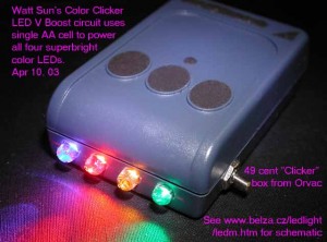
I built this in April, 2003.  It uses a single AA cell and a 2 transistor V Boost circuit, see pic for the link.

default

2012-07-24 Cat’s Whisker Detector for a Crystal Radio

Whilte I was writing my blog about Homemade Components, I visited the Wikipedia page about the cat’s whisker detector, the active component in the crystal radio.  I read the intro paragraph

“A cat’s whisker detector (sometimes called a crystal detector) is an antique electronic component consisting of a thin wire that lightly touches a crystal of semiconducting mineral (usually galena) to make a crude point-contact rectifier. Developed by early radio researchers Jagadish Chandra Bose, G. W. Pickard and others, this device was used as the detector in early crystal radios, from about 1906 through the Second World War. It gave this type of radio receiver its name. It was the first type of semiconductor diode, and in fact the first semiconductor electronic device. The term cat’s whisker was also sometimes used to describe the crystal receiver itself. Cat’s whisker detectors are obsolete and are now only used in antique or antique-reproduction radios.”

and several things struck me as being out of place.  I’ll try to explain why I think these should be changed.  I am pointing these out because I think they have insufficiencies, and I leave it up to the authors to decide whether or not they need to be changed.

The wiki says “antique electronic component” which I think implies that all cat’s whisker detectors are very old.  These are still being made for crystal radio enthusiasts and it is likely that if anyone sees a cat’s whisker detector, it will be a reproduction only a few years old, not an antique.  I would say “an electronic component originally from the early days of radio” or something similar.

They then go on to say “crude point-contact rectifier” which I think is an indication more of the author’s point of view today, rather than the actual situation when it was invented a century ago.  I would say “.. was a better detector for its day, but was later superseded by much better detectors.”

They then go on to make the claim that “..in fact it was the first semiconductor electronic device.”  I think that one could argue that since carbon granules are neither conducting metal nor insulator, they are a semiconductor.  Therefor the carbon granule microphone first invented by Thomas Edison was arguably the first semiconductor electronic device.

One may also argue that the selenium photocell, the selenium rectifier, the copper oxide rectifier, are from the very early days of electricity and may predate the crystal detector as the earliest semiconductor electronic device.

© RustyBolt.Info/wordpress
CyberChimps