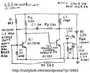
 This circuit is from a bunch of drawings that I have from the years before I started drawing circuits on the PC. It was drawn Jan 8, 2004 and built the next day. The design is much like those found on websites and in electronics magazines with the exception of D1 and R4. I’m not sure exactly what D1 and R4 are supposed to do. D1 seems to be protection to keep the base voltage from going more than 0.6V negative, but it could also have other effects on the circuit. R4 seems to be a feedback to stabilize the output. As the LED current increases, the current through R4 increases and causes Q1 to go further into saturation, and changes the on/off time of the oscillations. This should stabilize the circuit and make the light output less dependent on the battery voltage. There is a slight penalty: the LED current flows through R5 and the voltage drop wastes a few milliwatts.
I don’t remember seeing the circuit in my collection of similar circuits – I may have disassembled it. I have no further information on how well it performed. Back then I spent a lot of time in the Usenet newsgroups sci.electronics.* and alt.binaries.schematics.electronic, and I may have found the schematic there. Many of the people there were professionals* and were very helpful with problems. But a few really bad apples spoiled the newsgroups for the rest, and the spammers were flooding many newsgroups with spam (there are many specialized forums that are moderated and don’t have the problems that the unmoderated newsgroups have). Since I found that those forums had most of what the newsgroups offered, I stopped participating in Usenet. Several years later I visited the newsgroups briefly and found that the same losers were causing problems, so I stopped and haven’t been back since. I also found that I was no longer wasting a lot of my time.
Back to experimenting…
*One was Winfield Hill who co-authored “The Art of Electronics”, an excellent text for the serious student of electronics. Even though the book is expensive, I highly recommend it.