


When I work on a Joule Thief I need a power supply that will go all the way down to zero volts. Kirk pointed me to a high current power supply (6 to 8 amp) that puts out zero to 30V and uses a LM317. I have built a power supply that uses a LM317 and goes to zero volts, but it has some very nasty problems (here is a picture of it). Kirk’ss power supply uses a different approach to get the output to zero volts. The designer put three diodes in series with the output of the LM317 to drop the voltage before it gets to the two power transistors.
I believe that every power supply should include the D6 and D10. These protect the power supply. C8 and C9 reduce the output impedance. The fuse in the output protects the PS from overcurrent. But I think the fuse should come before C8, not after.
Deficiencies
There are some deficiencies, one serious. I think t he two 4700 uF filter caps at the output of the bridge are not enough to give good filtering at 6 to 8 amps. Somewhere way back in time I read that a good rule of thumb is you need 8300 uF for each amp of current. But that may have applied to audio amplifiers, not regulated power supplies. I would add at least two more.
Another is that at very low voltage and very high current output, the power transistors have to dissipate over 150 watts, so a very large heatsink is required. The power transformer secondary has a center tap, and it would be simple to add a range switch that uses only half the secondary when the PS is on the low voltage range. This would cut the dissipation in half.
The most serious deficiency is the output is open loop – there is no feedback to keep the output equal to the output of the LM317, which is capable of very good regulation. As the current changes from 0 to 6 or 8 amps, the voltage drop across the three diodes, the transistors and the two 0.1 ohm resistors could add up to a volt or more. The drop across the two 0.1 ohm resistors will be 0.4 volts at max current. These drops are not compensated by the LM317, so this power supply does not have good regulation. And this is especially true at low voltages, where the regulation may vary from 3V at no load to 2V at full load. That’s a 50 percent loss.
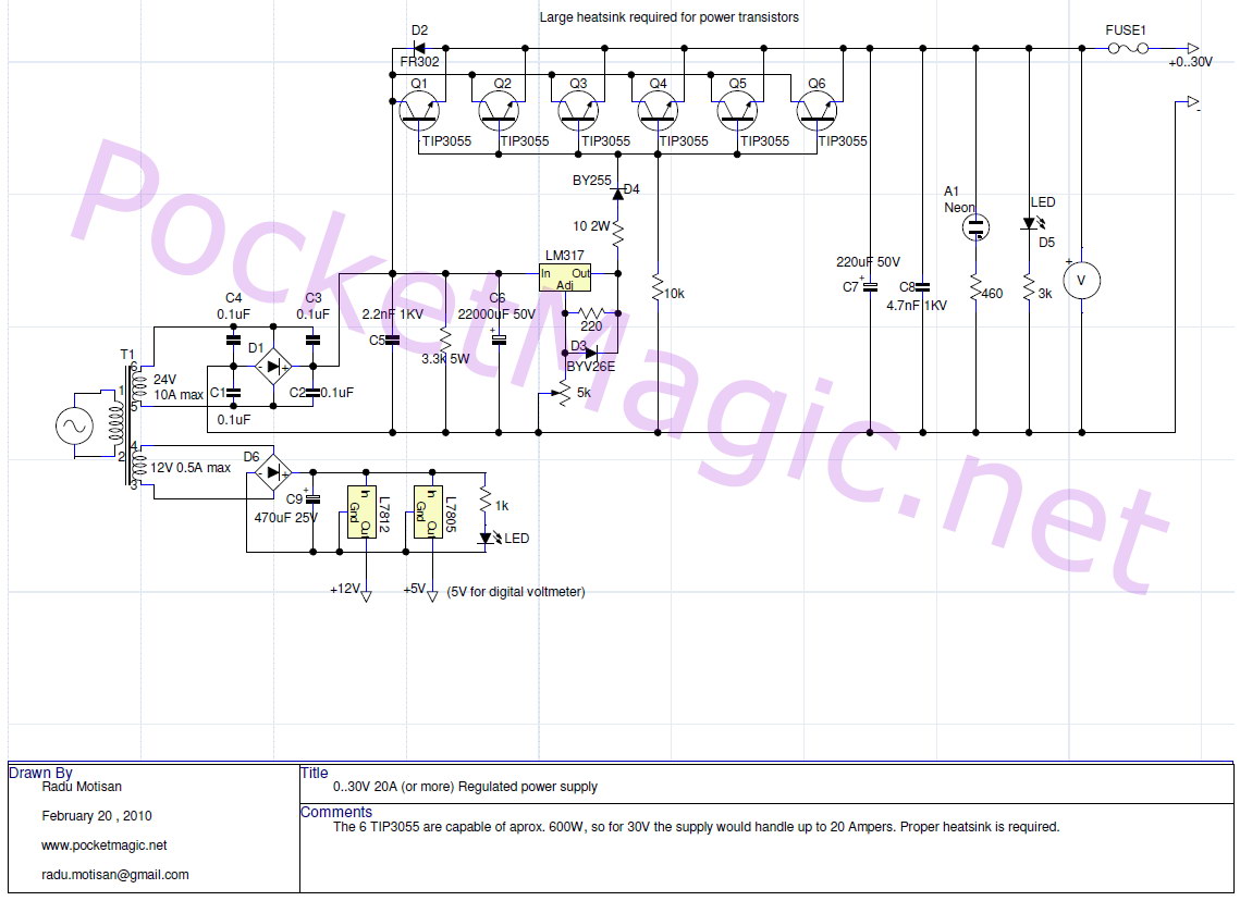
Second PS
The second power supply link that Kirk sent is similar to the first one above. It uses six 2N3055 power transistors in parallel for a huge amount of current – up to 20 amps. It also is open loop – the output will vary depending on the load.
Oh, one more thing – I forgot to mention another very big gotcha. Both of these power supplies use a power transformer that is very expensive. Mouser wants more than sixty dollars for a 24VAC, 10 amp transformer, and that doesn’t include the shipping cost – they’re very heavy. About the only solution for the average experimenter is to modify a MOT (microwave oven transformer), by removing the secondary wire and then rewinding it with some heavy copper wire. It shouldn’t take that many turns. There is more info on MOTs online, so check to see how others have done it.
IP ‘borrowing’ – Also, there are some electronics websites that plagiarize other electronics websites. Down in the lower right corner of the schematic you will see qsl.net/ON6MU which is where this schematic apparently originated, but the URL says electronics-diy.com. I am not accusing this website of plagiarism ( ON6MU could’ve given permission), but there are many electronics websites that steal the schematics of other websites, put their name on it, and offer it as if it was their original schematic. I have often seen newer websites that have schematics identical to websites that have been online for more than a decade and the newer website has erased the original name from the schematic, and put their own name on it. I vote with my feet: I don’t patronize these websites when they come up in a search. These websites depend on your eyeballs to sell the adverts that are ever present, and the more hits they get, the more they make. So please don’t patronize them once you have found out about their shady reputation.
The second link has the website as a ‘watermark’ across the whole schematic. They put this on the schematics to try to prevent others from stealing their schematic. Problem is it’s very easy to remove – takes me less than a minute to change the contrast in Irfanview and eliminate the watermark. Funny thing though. I’ve found that the websites that try to protect their images with watermarks are most often the ones that have stolen the schematics of others.
Another reason to avoid these websites is once they make the copy of the original, any later additions or corrections are lost, so if you use the copy rather than the original. you may be getting an inferior copy with errors or omissions.


A transformer from a stereo amp or a reciever amp will do, and will have other windings for constant voltage outputs. Will also have larger caps to salvage.
It’s kind of a shame to cannibalize a solid state receiver or amplifier when all it probably needs is output transistors. Maybe I’m just being sentimental, but if the amp seems to be repairable, I usually repair it.
So how many do you have? Out of the 7 A/V recevers I found this year 3 worked and the other 4 I stripped for free parts, and I’m sure I will find a few more. This is how I get 95% of components etc to make other things.
Several, I’m not sure how many. Most of them were boxed up and stored in my garage a year ago when I moved. I have a couple Heathkit tuners and a few audio amps in my conglomeration of audio equipment in the living room. In the past I’ve salvaged a lot of parts out of computers, CRT monitors , industrial equipment, TVs, tape recorders/players, etc., etc. I used to live near a busy freeway and I think it contributed (ozone, sulfur, etc.) to a lot of deterioration of rubber and other materials of the stuff I collected. Old electrolytics tend to leak or dry up and need to be replaced. So I guess some of the old stuff just isn’t economically repairable. Today I took a heat gun and heated up a PC board and let the parts drop and fall into a box, and later picked out handfuls of caps, transistors, chips, whatever. I must have hundreds of pounds of parts, much of them new. I’ve also taken a ton of stuff to the e-waste place to free up some room. I moved into a bigger house, but maybe I should have moved into a bigger bigger house?? :-p
I have the same problem, lately when I see something on the road side I keep driving. But the good thing is if you fry a component it was free and I have 20 or 30 more. The most of 1 thing I have is micro wave oven diodes, around 150. No room on the bench any more.
Holy smokes! A MOT (microwave oven transformer) is a lot bigger than the diode, I hope you don’t have that many MOTs! I have a few, and I cut the HV winding off one; I was going to try rewinding it with some 10 or 8 gauge wire to make a spot welder or something. They’re buried in the pile of boxes I put in my garage when I moved last year. Someday I’ll drag them out ad see what I can do with them.
I think there are about 80 MOTs in the shed. Imade a spot welder, I used 2/0 welding cable but only 3 turns fit so I got 2.5 volt and my amp meter will only read up to 1325 amps. Works ok for thin sheet metal and small rod. Will make another one some day but at 4-5 volt.
I think that if the core is wound with several windings of smaller wire in parallel, it may allow more turns on the core. It would take five windings of 6 AWG wire in parallel to make the equivalent of 2/0 wire. It may be possible to use smaller wire with more turns, since the duty cycle is low and the heat will have time to dissipate. Thanks for the pictures. They give me some good ideas. The only thing that I haven’t a clue is what to use for the electrodes.
I’ve been trying to reply to my emails but I keep getting server hangup error messages almost all the time. I’ve apparently lost some replies, and I may have replied more than once to an email because of the errors.
Odd about your email. I think the electrodes I used are the tips from very old soldering iron, they are in the holder upside down so you can’t see the chisel end. I think also the copper holders are from the same. Found them in an old junk store.