The author of Designing With LEDs has been especially busy with posting interesting articles lately. This article is about LED filaments from a Chinese seller. Closeup photos show the insides of the LED strings.

2015-04-25 Transistor Tester Kit Does More
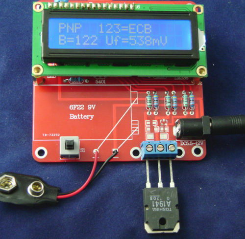
A few weeks ago I ordered this kit on a whim, not knowing what to expect, just something to assemble and get some soldering practice (this is what it looks like). There are several Chinese vendors that sell them. The info claimed it tested other components besides transistors. It shipped from China so it has taken a few weeks to arrive. It says transistor tester, but I was pleasantly surprised to find that it does many other things, which I talk about at the end.
This kit consists of a double sided phenolic circuit board, a back-lit display, an Atmel microcontroller and socket, a 9V battery clip, switch, trimmer pot, and an assortment of other components. All of the resistors, to my surprise, were 1 percent tolerance.
I would like to warn others that this kit comes with no documentation at all. You’re completely on your own with no help at all. For this reason I would say that it is not a beginner’s or intermediate kit; it needs a kit builder with experience. There are some parts that don’t match the labels on the board. So if you intend to tackle it, then find someone who can help you if you find yourself lost.
I got to work and stuffed the resistors, capacitors and a few others that stayed in place, and soldered them, clipping the leads as I went along. The 1% resistors are a blessing and a curse. They provide extra accuracy but it’s likely that many of them could be 5% with no difference in performance. But for the typical technician who is used to reading 5% resistors, it’s a lot tougher and slows things down a lot. If you have any doubt about the value of a resistor, check it with a digital multimeter to find its actual value.
After I had finished stuffing and soldering the resistors and “104” and “103” capacitors, which all matched the labels on the board, I found a 102 label on the board. Well, 102 is the same as 1 nF, which was a yellow cap marked 1nfJ100 on the top. The two 22 pF holes are filled by small disk caps marked 22, nothing else. The white line on the electrolytic capacitors should line up with the line on the board. I found that the ‘lytics caps must be fully seated to allow the display to be screwed all the way down to the board.
The metal package marked 8.0 is the 8 megahertz crystal that’s close to the two 22 pF caps and the microcontroller. The power jack goes in only one way, but the pushbutton switch should have a line on one side, which goes towards the edge. Line the socket up so that the notch on the end lines up with the label on the board, which is the edge of the board. I haven’t soldered the battery clip in because I have a 9VDC wall wart adapter that fits the power socket. The jack is 5.5 by 2.1 mm. This MUST have the center pin positive. I just have to get an AC ‘wall wart’ adapter for it from my junk box. The jack says 5.5 to 12 VDC, but the wall wart I used was 9VDC unregulated, and when it is first turned on it displays the supply voltage, which read 13 point something, depending on the AC line voltage. It accepts this with no complaint.
I chose to solder the display male 16 pin connector to the board and the female socket to the display, but either way should work. I had to bend the LED out to the outside to get the display to seat completely. Some transistors were nearly touching the display so it’s best to make sure they are seated well before soldering.
When I finished with double checking the parts and making sure the Atmel chip was inserted properly, I assembled the display with the two studs and four screws provided. I checked the parts to make sure they were not preventing the display from seating fully. I had to bend the LED over a bit.
After I again double checked everything, no loose or unsoldered pins visible, I decided everything was ready for power up. I plugged in the power and the display lit up, but there were no letters on the display. I adjusted the trimpot, which is the display brightness, and the letters appeared in the display. The top row of pixels on the second line were blank, so I tried seating the display onto the board, and the pixels lit up. I’m not sure why, but if it comes back, I’ll have to resolder the pins.
I connected a few disk caps to the left and center pins of the three pin screw block and pressed the button switch. It identified the part as a capacitor on pins 1 and 2 and the capacitance was correct. I decided to add alligator clips to make it easy to change parts.
I got some 562.2 ohm, 1/10 percent precision resistors and tried one and it showed a resistor and a value of 562.8, which is very close. Some of the difference is the fraction of an ohm in the clip leads. I tried a red LED and it identified it as a diode, with 2.16 volts forward voltage. Cool! The LED blinked on and off during the test.
So far, it’s working very well on an LED, caps and resistors. I still have to try inductors, transistors and FETs. And a bunch more resistors and caps to see now accurate it is over a wide range. The inductors are my main interest because many L meters have difficulty with measuring sub-microhenry and multi-henry values.
I connected a BUZ71A to the three leads and it gave me the polarity, pinouts, the Vt=3.43V, and the C1.18nF.
I connected BC550C to the leads and it gave the pinouts, polarity, the beta and the Vf, presumably base to emitter.
I connected a 1N5817 Schottky diode and it gave me the pinouts, junction capacitance was zero and the Vf (forward voltage)=208mV. With a rectifier like the 1N4002, it gives the junction capacitance which is an indication that if the capacitance is high, say a few hundred pF, then it’s not a high speed, fast recovery rectifier.
The great thing about this tester is that I have many house numbered devices such as power transistors that I have not bothered to use because I’m not sure of their polarity and/or pinouts. Now I can connect one up, press the button, and in a few seconds it gives me the polarity, pinouts and tells me if it’s a transistor or whatever. I have already found one power transistor that is shorted and open so the tester thinks it’s a zero ohm resistor on two pins.
To throw it a curve, I turned it on first. Then I connected a 1.2 V rechargeable NiMH cell to it and pressed the button. After a much longer test time, it blurted out “Cell!” Heh, I thought I could fool it!
I haven’t tried any inductors yet, so here’s my next batch of tests.
I tried a 0.1 uh or 100 nH coil, but it tested as a 0 ohm resistor. Seems there’s a minimum value for coils that the tester can detect – it will test at least a .02 mH or 20 uH choke. I then tested a few 180 microhenry chokes and the test showed their resistance, about 2.1 ohms and the L, about .17 to .19 millihenry. I tested two 1mH chokes, and it said 1.01 mH and 4.8 ohms. I tried a few 100 uH chokes and it said .09 to .10 uH, but with only 2 digits of accuracy, the resolution isn’t very good. I then tested a 33 uH choke and it said 0.1 ohm and .03 mH. It read the value of the choke, but again with poor accuracy; the actual value could be from .026 to .034 mH and it would still read .03 mH. So I would say that it’s not very useful with any value below .1 mH.
I tested a winding of a transformer on a ferrite core, on which was written 3.6 mH, 1.5 ohms. The test gave 3.4 mH and 1.5 ohms. Pretty good.
I tested at least a dozen chokes of various values, most of them less than 1 mH. The results were consistent, but due to the two digit values, the values were of limited accuracy.
This component tester is very useful since it combines so many component tests into one piece of equipment. I find it interesting and useful. Its performance is good and it’s inexpensive but it is a kit that must be assembled. If you can buy it assembled, I would recommend it for the hobbyist since it does so much for such a reasonable price. But as a kit with no instructions, it’s a lot tougher than one might think.
There is a plastic box for sale separately, but I plan on mounting it in a box I have.
I’ll try to find docs online.
Update May 1 – I ordered a second kit online from a different vendor in China. It arrived a day ago so I assembled this kit today. All of the resistors were 1 percent, as were the ones in the first kit. I stuffed some resistors into the board and I came to one resistor that was orange, orange, black, red, brown. This is 3, 3, 0, two zeros, and brown equals 1%. That’s 33,000 or 33 k ohms. The board didn’t have a label for 33k, but it had 3.3k. So I left it for later.
After I finished with the other parts, I had the 33k resistor and an unfilled place on the board labeled 3.3k. I measured the resistor and it was 33k, not 3.3k, so the kit came with the wrong value resistor. When I started, I noticed that the first kit had some part numbers where the battery is supposed to lay. But this second board has no numbers, so my guess is that this is a “knockoff” kit made by someone who stole the plans from the originator. I think the resistor is part of a voltage divider that goes to one pin of the Atmel microcontroller, and is probably important as a voltage reference. So I need to scrounge through my box of precision resistors and find a replacement. I found a 1% 3.3k resistor and soldered it in. Bingo! I powered it up and put a 187 ohm 1% resistor across 1 and 2, and it said 186.2 ohms – Good! Very close!
So now I have two of these little beasties up and running. One for the test bench and another for tossing in the tool box or as a backup. For that, it really should have a case. I saw one online, so I’ll have to check into getting one or two. Or else getting one of the boxes out of my collection and hand making one. Too little time and too much money so I’ll probably buy one.


2014-04-21 Man Shoots Computer

It’s a Dell. Man, I’ve known that feeling a number of times!
I’ll bet the guy took the cover off, took it out and shot at it, then put it back on. There’s nothing wrong with the PC except it’s got a few more ventilation holes!
2015-04-20 New Cree T8 Fluo Light Replacement
Designing With LEDs has a new review of a Cree LED T8 fluorescent light replacement.
http://www.designingwithleds.com/the-new-cree-tw-series-led-t8-review-and-teardown/
The price has dropped significantly – from $30 US down to $22 US per tube. One important thing that I got from this review is that the old ballast decreases efficiency and wastes power, so it’s better to rewire the fixture and disconnect the ballast. That’s not easy for the average homeowner to do; it should be done by an electrician.
2015-04-19 A Way To Check For LED Lamp Life
I was reading that someone speculated that LED lamps may fail before the 25 thousand hour ratings claimed by many manufacturers. This can be caused by failure of the circuit that drives the LEDs, not the LEDs themselves. The most likely components to fail are the electrolytic capacitors, because they dry out or leak the electrolyte.
I have a few AC line powered LED lights that are inexpensive and have very simple circuitry, such as Christmas tree lights and low wattage candelabra base lights. I can tell that they have simple circuitry because when I move a pencil rapidly back and forth under the light, I can see the pencil not as a blur, but as a string of images caused by the flashing LED light.
This strobe effect indicates that the current going through the LEDs is not filtered. To save money, some makers rectified the AC but did not filter it with an electrolytic capacitor to save money. With no electrolytic capacitors to fail, the light should last longer. There could be other factors, such as running hotter, which could shorten its life. But this flickering is one way to find out whether or not the light has filter capacitors, which are usually electrolytic.
One other factor is environment. If the environment is harsh, the light may fail prematurely. If the light gets hot from direct sunlight; if the light is in an enclosure without ventilation; if the light is mounted so the heat from the LEDs rises and heats the circuitry; all of these factors may contribute to a shorter lifetime.
Some circuits are designed to slow the very high inrush current when the light is turned on. If the maker decided to eliminate this to save money, then the strain of high inrush current may cause the circuitry to fail, especially if the circuitry is is turned on and off frequently.
These are some of the factors that can influence the light’s lifetime. If the manufacturer makes a LED light that lasts for a very long time, the light will seldom need replacing and light sales will drop. So the light designer wants to design a light that lasts for a “reasonable length of time.” What is reasonable will not be known by the consumer. My guesstimate is longer than the warranty, but shorter than the lifetime of the LEDs.
2015-04-18 Spectrometer On Your Keychain
I’ve been playing, er, experimenting with Geiger Counters recently, just to satisfy my curiosity. My mind’s curiosity area went into hyperdrive when I found out about this device. Just think! A detective could examine a hair to check for arsenic to see if the victim has been poisoned! Wow! I can think of other, less morbid uses for this fascinating tool. One could go out on a glacier and check to see if a pebble is the remains of a meteorite. A doctor could examine a drop of blood for anemia, or who knows how many other things for a diagnosis. On the spot, with no waiting a week for lab results! You could check for food adulterants, and you might be shocked at what you find! Coca Cola should be worried about their ‘secret formula!’ This is the first step in creating the food replicator (tea, Earl Grey, hot). Chem labs can check supplies for purity. And so forth, and so on. The possibilities are limitless!
http://m.fastcompany.com/3031411/this-keychain-dongle-can-analyze-almost-any-physical-object-instantly
2015-04-17 Power Plug, Switch
I do exercise, but when I’m reading couch potato style, I like to have my LED lights with a switch close by. So I make up extension cords with a plug, switch and outlet socket. I also like to put the on/off switch where the AC power comes into the adapter because there will be no transformer or circuit wasting power 24/7 even when the light is not being used.
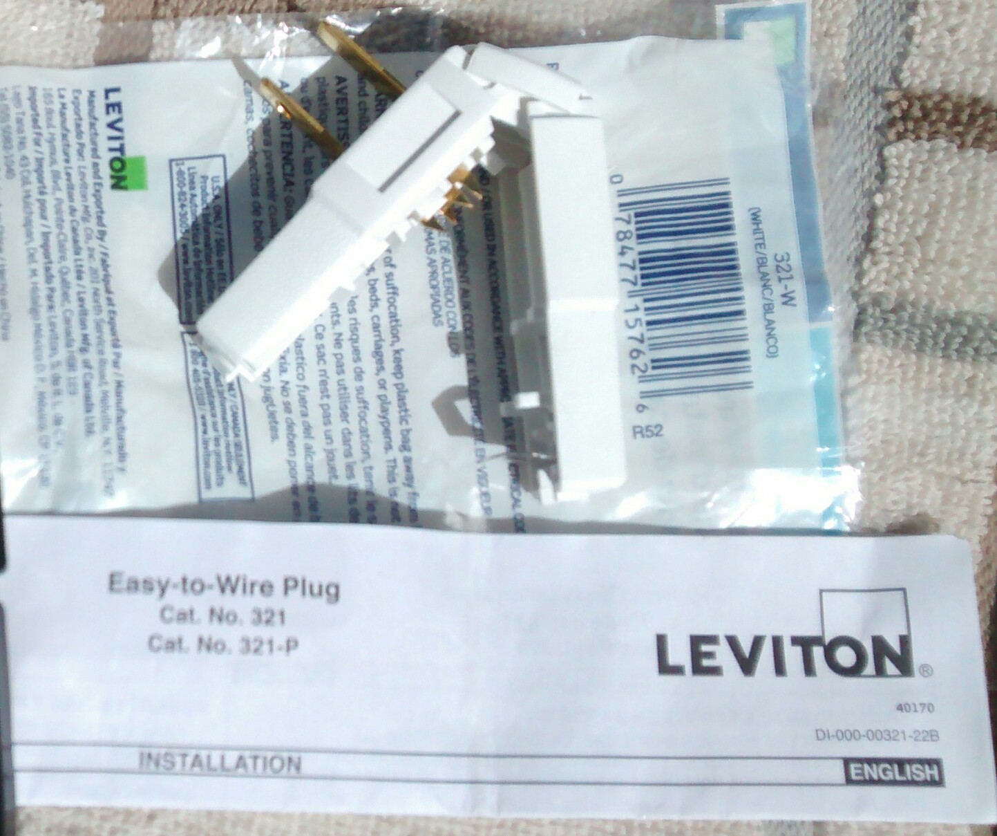
One problem that seems to afflict every power strip is the lack of outlets, often caused by large “wall wart” adapters taking up more than one outlet. That’s where this plug may help. It’s 1 inch or 25mm wide and the cord comes out the side so it may fit where other plugs won’t fit.
I list some of the other advantages below.
It comes with one page of instructions as shown in the photo.
The one piece plastic body comes in white, brown. The body snaps together so you can open it with your fingernail, and squeeze it closed until it snaps shut.
The 18 AWG, 2 conductor lamp cord is cut squarely and laid in the place for the wires. The wires do not have to be stripped because the prongs pierce the insulation. The two body halves clamp the wires and hold the cord in place. The body is closed until it snaps shut, and that’s about all there is to it.
The two prong plugs come in polarized and non-polarized versions. Polarized has the neutral prong larger than the hot prong. This power plug is suitable for most AC adapters, which usually have only two power prongs and no ground pin is needed.
I used a small inline switch typically used in the cord of swag lamps. It has a small knurled wheel that is turned, alternating between on and off. These have been in use for decades, are inexpensive and do an adequate job.
I’ve also used the remote control power switches such as the ones made by Stanley. These typically come in a kit with 3 or more switched outlets and a single remote fob with buttons for each switch. Problem is that I soon run out of them and the frequency bands are limited – you don’t want to turn on multiple outlets with the same button at the same time. One other consideration is that the remote switch may waste as much power as the device you are trying to save power. The remote switch must have a receiver, which may only take milliamps of AC current, but it has to be on 24/7, and wastes that power all of the time it’s on. Since that problem is eliminated with manual switches, I try to do my part in conserving energy. The most efficient way of saving energy is to not use it.
2015-04-14 3D Printer Under $200
QS sent me an email with a link to Tiko 3D Printer that will soon sell for $179.00
It isn’t in production yet; it’s a crowd funded operation. They give more info on their website. I have a problem judging the size of the printer. It could be small and only print small objects the size of the palm of your hand. But the price is very attractive.
2014-04-13 Joule Thief As Armstrong Oscillator
In the wiki for Joule Thief on Wikipedia, someone claimed that the Joule Thief is an Armstrong Oscillator. I dispute that claim and prove it’s wrong in the following discussion.
An oscillator is capacitance and inductance ( j.omega )that forms a resonant circuit, and according to Barkhausen criterion, an amplifier that is a linear circuit and excites this resonant circuit by maintaining its oscillations by replenishing the losses during oscillation. The resonant frequency is the point of minimum loss, so the circuit operates at this frequency.
The Joule Thief does not have a tuned circuit because there is no capacitor. It also is not a linear circuit – it operates as an on/off switch. Some claim that the capacitance is the parasitic capacitance of the circuit, most of which is the collector capacitance of the transistor. Typical transistors used in this circuit have about 3.5 picofarads capacitance.
Using a typical coil, the inductance of the collector winding is about 100 microhenrys. With 3.5 pF capacitance across the coil, the resonant frequency would be more than 8 MHz. The typical Joule Thief doesn’t operate at 8 MHz, it operates at 100 times lower, or about 80 kHz.
The Armstrong Oscillator puts out a sine wave at about the resonant frequency of the capacitor – inductor combination. But the Joule Thief operates 100 times lower, or about 80 kHz, which is much lower than the resonant frequency. Therefore, for the above reasons, the Joule Thief is not operating as an Armstrong Oscillator. The Joule Thief is operating as a relaxation oscillator, using the inductance and resistance of the circuit as a flyback voltage booster. Thus the Joule Thief is simply not an Armstrong Oscillator.
Check references other than Wikipedia. It can’t be any simpler.
2015-04-09 Power Lines Jump Rope
I thought this YouTube video of power lines playing jump rope was really cute. It took a bit of work to make this video. And it looks like it has been around for a couple years.
But to show how serious this is, I thought I should explain a few things about these high voltage power lines. Generally these are called transmission lines because they get the electric power from the generation point to points where it is distributed. Because generation points such as power plants make such a huge amount of electric power, the power lines have to be very heavy and high above the ground, on pylons as seen in the video.
I’ve seen the ‘wires’ lying on the ground before they were hung on the pylon at a huge switchyard near where I live. This ‘wire’ is very large, about 1.5 inches or 38 mm in diameter. That’s a lot bigger than a typical wire. Even though the wire is mostly aluminum, it is still very heavy. The insulators that hold them up must carry many tons of weight.
But the truly amazing thing about these lines is the amount of electric power they carry. They can handle billions of watts, in other words, millions of kilowatts, or thousands of megawatts. That’s enough to power a large city of a million people. You can see videos of maintenance workers working on these live power lines on YouTube.
The current is thousands of amps, and the voltage is hundreds of thousands of volts – one common American voltage is 245,000 volts or a quarter million volts. The arc can be wider than your outstretched hand. If these lines were to come close to each other or to the ground, there would be huge sparks, like lightning. If you got between the lines, you would be burned up in fireball in a few seconds. BZZZZT! Crispy critter!
So if you see those power lines playing jump rope, watch out! Sparks will be flying in an instant! 😉