


I built this superregenerative FM broadcast band receiver today. This circuit is similar to the one I posted on January 22.
Here is a list of parts values I used:
ANT – 12 cm insulated wire connected through 10 pF capacitor to FET source.
C4 – two 2.2 nF MLCCs from + to ground plane ( I built this on a small piece of copper circuit board.)
C5 – 18 pF silver mica capacitor
C6 – not used – replaced with a jumper.
C7 (A and B) – two 0.2 to 5 pF plastic variable capacitors
C3 – 10 pF silver mica capacitor
R1 – 10k 5% carbon film resistor (May 7 I changed this to 3.3k, then 2.2k.)
R3 – 2.7 M 5% carbon film resistor
R4 – 22k 5% carbon film resistor, later reduced to 11k to help make earphone louder.
Q1 – 2N3819 VHF JFET, later BF256 and BF244.
Q2 – C9018 high gain low noise NPN BJT similar to MPSA18.
L1 – 6 turns 20 AWG bare copper wire wound on drill bit shank, appx 6mm ID. Coil stretched so it measured appx 120 nH.
L2 – 6 turns 24 AWG solid insulated wire on a FT37-43 toroid core, measured 14 uH, later rewound to 33 uH, cut back to 25 uH.
(Some of following copied from FB post)
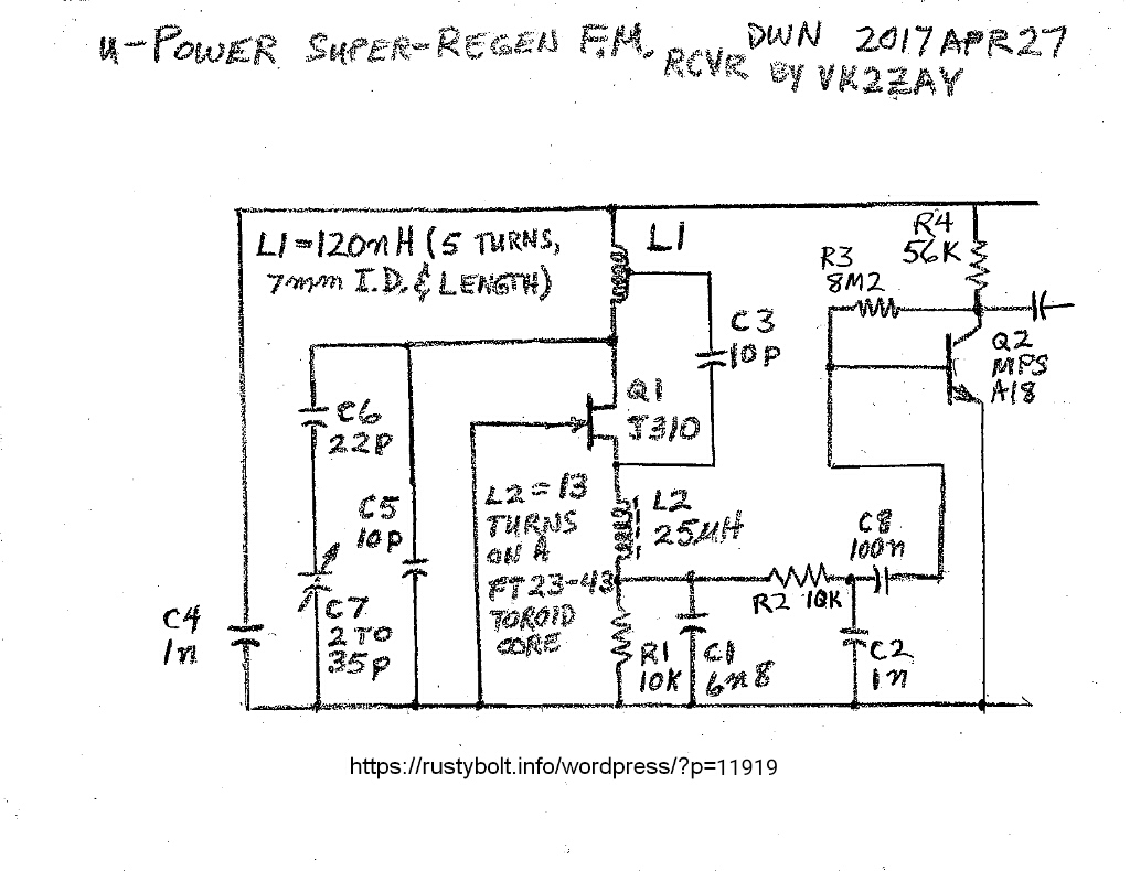
My Superregen won’t quench. I built the circuit found here, with a few changes.
http://www.vk2zay.net/article/129
I used a 2N3819 for Q1, and a FT37-43 for L2, measuring 14 uH. At the end in his notes he gave some limits to the values of some parts, and the values I used seem to be within the limits.
For an antenna I connected a short 12 cm length of wire to the FET’s source, as he recommended. The coil is 6 turns of 20 AWG bare copper wire, wound on a drill bit shank, and spread out untl it measured about 120 nanohenrys. I used an 18 pF silver mica capacitor and two 0.2 to 5 pF variable capacitors in parallel with the coil.
I used a dip meter to tune the coil and capacitors to a point within the FM broadcast band. I measure a little over 2 volts at the source, so the JFET is conducting in the linear region.
I used a scope to check the R1 – C1 point and I see no oscillations. I’m using 9VDC regulated for the supply. I connected the Q2 output to an amplifier and I get noise like a hiss but no stations. I can hear my cell phone burps loudly, and hum if I touch points in the circuit. So I’m fairly confident that I have the circuit set up properly – no major malfunctions.
I just thought of one thing I can do. I can put the circuit on a variable supply and try various supply voltages. I’ll try that and update this.
Update evening until 1:30 AM – I experimented with several different parts. I put it on a variable supply and it seemed to do a little bit better at 6 volts. At the beginning of this session I could receive only a single FM station, one that’s very close and powerful. This was with the 12 cm wire connected through a 10 pF capacitor to the source. I couldn’t hear any other stations.
I removed the L2 and rewound it, so it has 9 turns on the FT37-43 core and measured 33 uH. The audio seemed to be louder. But as I tune, the audio is garbled, seems that the level is too high for the audio amplifier I’m using. Still only one station.
I moved ‘center tap’ one turn closer to the positive end of the tank coil. I also spread the turns a bit, and adjusted the variable capacitors a lot. I think the coil could be longer and lower inductance so it will cover the high end of the FM band.
I searched online for more information about this regen design. I found another builder’s story of the problems he had with his regen. He used too much bypassing capacitance, so he reduced it and the regen started to quench. So I also reduced mine. I changed C4A and B to a single 1 nF capacitor as shown in the original schematic. But it still doesn’t work.
Update Evening Apr 28 – I was looking at a tiny .jpg I had saved of the pinouts for the 2N3819, and I noticed they were backwards. Instead of S G D, the pic showed D G S. So I checked three datasheets to see. The ON Semi showed S G D, the Temic showed S G D, and the Central Semi showed D G S (!!!) So what brand of JFET was in my circuit? Oh, no! It was Central Semi! So I removed the 2N3819 and flipped it over, and soldered ot back in. Now I tuned for the strong station but I couldn’t hear anything on the earphone. The one thing I was certan of was that there was uncertainty on what the true pinout was for the 2N3819 that I was using, so I decided to use another JFET. I chose a BF244, which I have plenty of, and it’s rated for VHF or better. After I installed the BF244, I still couldn’t hear the strong station. I was looking for a possible short, and I looked inside of the coil and found a blob of solder shorting turns. Once I got that out, the strong station tuned in, but I heard no change, just a single strong station. The voltage at the source was about the same as before, a bit over 2 volts.
So I got rid of a questionable JFET, but the replacement didn’t perform any better. I can hypothesize that the second JFET in this circuit with no change implies the poor performance problem is most likely not being caused by the JFET itself.
There’s an old saying that says “Amplifiers will oscillate, oscillators won’t.” Well this oscillator sure doesn’t want to oscillate, it just won’t quench.
Update May 2 – I spent a lot of time this evening trying to get a sound out of the circuit, but it was dead silent. I cut out the JFET and relaced it with a BF256B, and it started picking up a very weak signal. Apparently the JFET had died when I was unsoldering or soldering the various parts.
Update May 7 evening – I had been working on the 27 MHz Vackar ‘signal generator’ for a few days, among other things. Now I’m back to try and get this FM regen to quench or to squegg as some others have called it. One thing I had not experimted with was the JFET current. This is limited by R1, which has been 10k. The JFET’s current is less than a half milliamp, so I decided to reduce the resistor to get about a milliamp. I removed the 10k and replaced it with a 3.3k. Wow, this made a big difference! All of a sudden the earphone started hissing like a superregen is supposed to when it’s not tuned to a station. I checked the signal at the top of this 3.3k with the scope and it was quenching at about 88 kHz. The DC voltage was 2.4 volts, so the source current is still under 1 mA, about 0.74 mA.
I can tune it and hear only one strong station, but I hear quieting in the hiss at some other points, so it’s trying to pick up some not so strong stations.
The quenching starts at just under 9 volts supply voltage. If I drop below that, the quench and hiss stops. I think the circuit would work better if I reduced the 3.3k to let more current through the JFET.
I put a 6.8k in parallel with the 3.3k, so it’s equal to 2.22 k. I heard the strong signal, but it was garbled. I turned up the supply voltage, and as I passed 11 volts and got to 12V the audio cleared up. It sounded much better. The voltage across the resistors was 2.5 volts DC, so the JFET current was a little more than 1 mA. And I’m happy to say that this is the first superregen receiver that I’ve been able to hear a station clearly. And after many hours of tinkering I can say I’ve accomplished something.


