default

2018-04-05 Fake News And Right Wing Extremists – Guardian Article

From FB group Orange Talk

Don Thompson
All you have said, are, as you say, “a lot of fluff.” And the majority of Americans realize that. Sadly, you’re not in that majority.

You say the “mainstream propaganda … is not saying anything about the good…” That’s because there is so little good to say. Never before have we had a president snivelling and whining about the other branches of government like Grump has.

Gallup says “Lyin’ Trump” (to use his own words) has a 40% approval rating. That’s very poor – the American people are finally seeing the reality. If he doesn’t change, he’s never going to get reelected.

This article is from the Brits, who have no reason to be “fake news.”

https://www.theguardian.com/technology/2018/feb/06/sharing-fake-news-us-rightwing-study-trump-university-of-oxford

“If you’re not in the middle of the road, you’re in the gutter.” – Ike

default

2018-04-04 Transformers In Series Parallel Part 2

For FB group Building Transistor Radios

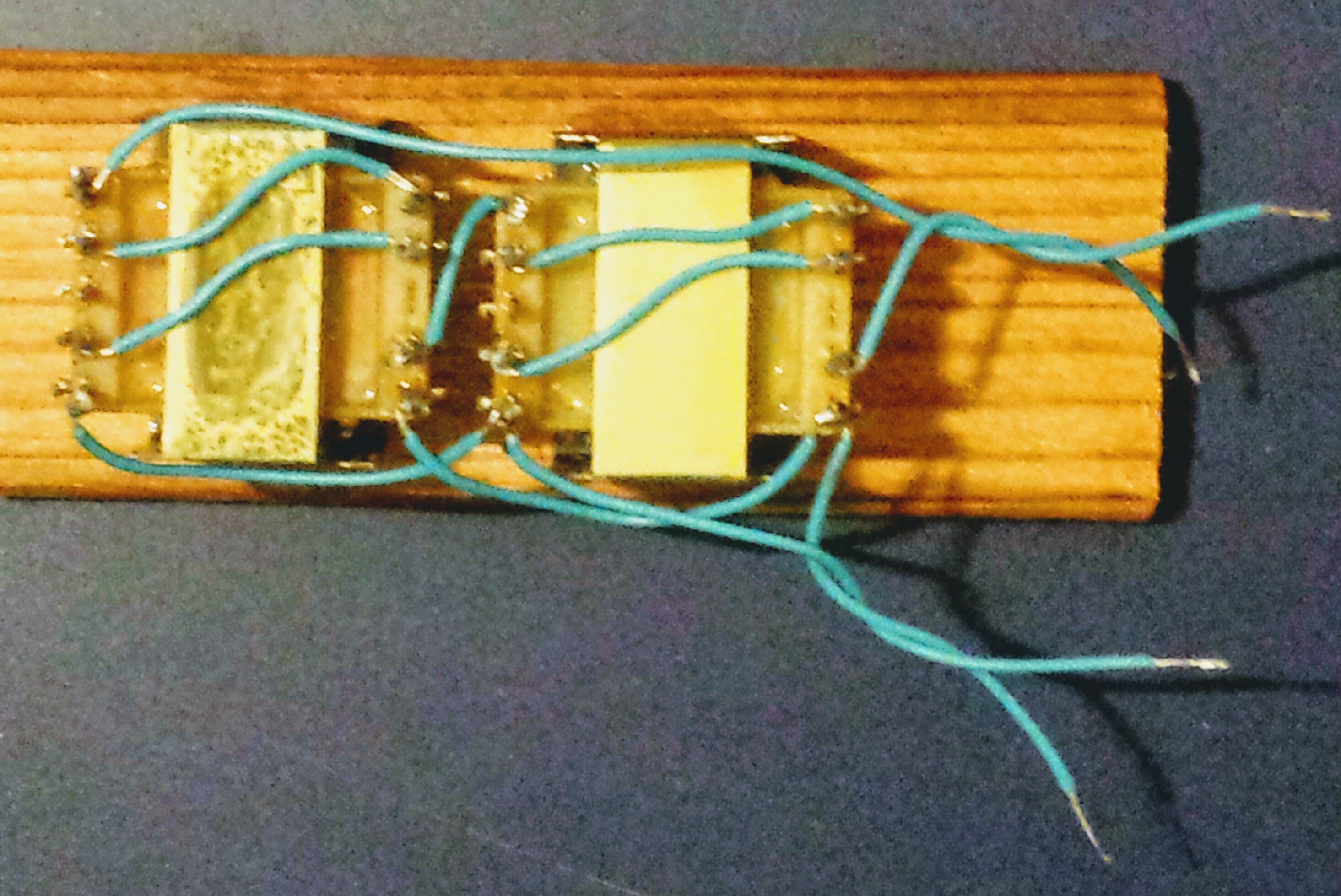
I rigged up two of the transformers, connecting six 600 ohm windings in series and two 600 ohm windings in parallel. I measured the voltages to find the turns ratio. I applied 6 volts to the 6 series windings, and measured 1 volt on the two paralleled windings. This gives me a 6 to 1 turns ratio.

The impedance ratio is the square of the turns ratio, or 36. I assumed the two 600 ohm windings in parallel give 300 ohms. So that multiplied by 36 is 10400 ohms for the six series windings.

default

2018-04-03 Transformers in Series Parallel

For FB group Building Transistor Radios

This is the idea that I had about using more than one transformer to connect their windings in series or parallel to get a higher impedance and a higher stepdown ratio. My idea was to be applied to the Bogen T725 line matching transformer, but it could be applied to any 2 or more transformers.

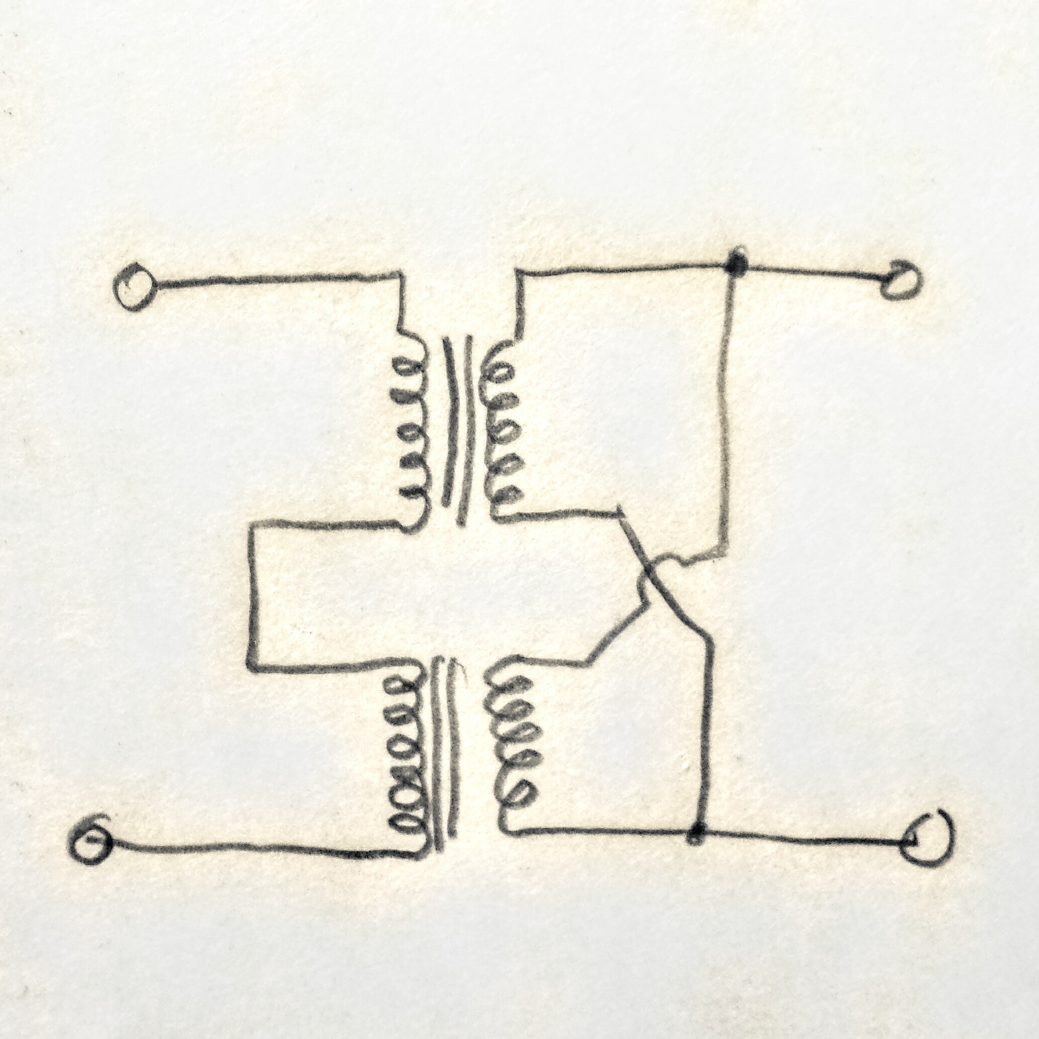
What I drew was a pair of transformers with their primaries on the left connected in series and their secondaries on the right connected in parallel. They must be connected properly, in phase, so they don’t cancel out each other.

When the windings on a single transformer are connected in series, the impedance is equal to the number of turns squared. This is because the voltage is double, but the current is halved.

But I don’t know if this ‘number of turns squared’ still applies to two transformers connected as shown in the diagram. In any case the series connected windings still have a higher impedance than a single winding. I guess the only play 2 find out would be to measure the voltage and current with the connections as shown.

default

2018-04-02 Student Financial Aid

From FB group Orange Talk

I’d like to tell you a true story. Back before Direct deposit, we (SAC) had to set up check handout tables for the students on Financial Aid. We had four lines, A thru G, H thruvM, etc. Each had an accordion folder with the checks sorted alphabetically.

One day I asked the disbursements lady how much was in the folders. “About a million and a half,” she said.

And that was a long time ago. Today it must be several times that much. All the grants and waivers that students in need get, you shouldn’t be complaining about what education costs the students. It still is free for many students. And they also have work for books program so students can pay $120 for a single textbook.

default

2018-03-30 Conserve Energy

From FB group Orange Talk

“So what’s your secret?”

Diligence. Turn the lights out. Use task lights like a desk lamp. Change every light to LED bulbs.

Use cold water for washing. The gas dryer saves a lot on electricity. Don’t use a hair dryer. Don’t use a toaster. Don’t use an electric coffee maker. Don’t use, or use very little of appliances that draw heavy power. Use a Bissell push sweeper instead of a Hoover.

Probably the biggest savings is due to the double paned windows and patio doors. Make sure the cold and heat isn’t coming in through the cracks in the doors. Fix the cracks with weather strip.

All these little things add up, if they are doing their jobs then there will be money saved. The utilities have literature online and hardcopy that can explain further. And the best thing is it helps to save our environment. 👍

default

2018-03-28 Wideband RF Amp In Royal 500s

From FB group Ferrite Loopstick Antenna Experimenters

Some experimenters in another group looked at schematics and saw that some radios with a RF amplifier between the loopstick and the converter used a third section on the variable capacitor to tune the RF amplifier. This is good, but it makes the variable capacitor more expensive and difficult to obtain.

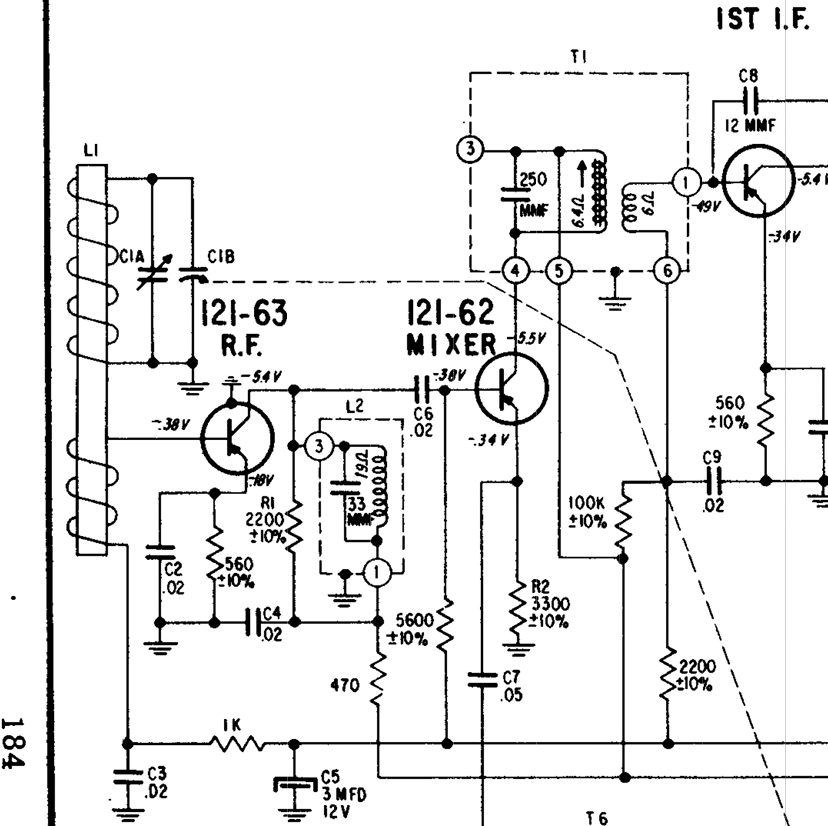
I have a bunch of truly vintage (1950s) Zenith Royal 500 portable radios, and some models use a RF amplifier, but with a standard 2 section variable capacitor. The model numbers begin with “8”, such as 8AT40Z2 (see attached schematic). These have the usual tuning capacitor across the loopstick to tune the input of the RF amp. After the RF amp, the collector load is another tuned circuit, L2, which is tuned to the middle of the AM band. This would give a peak in the middle of the band. But the designer put R1, a 2200 ohm resistor across the tuned circuit. The resistor changes the sharp peak to a flat plateau that has less amplitude, but it has about the same amplitude across the whole AM band – it has been changed into a broadband amplifier.

So the radio’s selectivity is given by the tuned loopstick, and the sensitivity is increased by the RF amplifier. Also, the transistor’s base bias is supplied through the 1k next to C3 which is connected to the AVC line. Strong signals cause the AVC line to reduce the gain of the RF and IF amps, which keeps the volume the same.

Here is where you can find this and other Zenith radio schematics:
http://www.transistor-repairs.com/schematics.html

default

2018-03-27

From FB group Vintage Transistor Radios

James Ault
Thanks for reminding me. I gave my 22 yr old car to my sister and after awhile the door started rattling. I found that the post that sticks out for the door’s latch to latch onto used to have a nylon sleeve, but age had caused it to fall apart. So I wrapped some 14 gauge copper house wire a few times around the post and the door stopped rattling.

So I’m thinking that a few turns of thin solid bare copper wire would work. The wire will not have the support that a copper sleeve would have. But after the washer, wire and screw have been checked for fit, the screw threads can be anchored with some cyanoacrylate Crazy Glue where the threads come through the motor board. The screw will not come loose, and if it needs to be removed, heat from a soldering iron will loosen it. 👍

default

2018-03-26 Reflex Receiver, 2 Transistor

For FB group Building Transistor Radios

Darrell Darby (Schematic below)
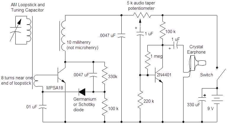
What amazes me is the collector load resistor for the earphone stage is 100k. That’s more than ten times higher than usual, and it’s okay because the crystal earplug is very sensitive.

I would squeeze a bit more gain out of it by removing the 220k and changing the 1 meg to a 4.7 Meg or 10 Meg. The 2N4401 is a general purpose NPN, you can use a BC547, PN2222A or 2N3904.

default

2018-03-25 Prepare For Changes To The 2nd Amendment

For the FB group Orange Talk

Brian Brice
Bob Takahashi
Jay Brown
In the late ’60s, there were protests that 18 year olds were old enough to die in Vietnam, but not old enough to vote. In 1971 the 26th Amendment was sent to the states, and *3 months* later it became a part of the Constitution. But you’re too young to remember that.

We’re a nation of oddballs to the rest of the world, which have implemented strict gun control in recent times. If enough people here realize how foolish we look to other *more civilized* and *less barbaric* countries, prepare for a whiplash, because things will change so fast it will make your neck snap!

Jay Brown
If you look at the 18th and 21st Amendments, they repealed the 18th, by adding the 21st to amend the Constitution. I think an amendment could be added to the Constitution to clarify the 2nd and give further guidance on gun control.

default

2018-03-23 tbd

First post to the FB group Ferrite Antenna

My first experience with measuring inductors came a few years ago when I bought an LC IIb meter from AADE. It’s a very accurate meter but has a few quirks.

I bought a bunch of small 100 uH chokes from a US company, and when I got them I measured one and it measured 78 uH. What?! That’s way too low! So I measured a bunch more and they all measured below 82 uH, way too low. So I contacted the company and explained what had happened. They agreed to a refund if I sent them back. Later their tech emailed me. When the guy got them, he measured them with various inductance meters, high quality ones like Hewlett Packard. The inductors all measured low, some were close to 100 uH but still out of tolerance. He couldn’t explain why the inductors were so far off, and why the different meters gave different measurements. But I did get my refund.

The only explanation I have is that the various inductance meters use different frequencies for measuring on the same range. As the frequency varies, the inductor’s material, such as ferrite, changes its magnetic property and the result is a different measurement.

The one way to get a meaningful measurement is to put a 1 percent tolerance capacitor in parallel with the inductor and find its resonant frequency. Then calculate the inductance using the frequency and the capacitor’s value.

The moral of the story is you can’t always trust an inductance meter to be accurate with every inductor.

Also, many inductance meters cannot measure very low values of inductance. Some meters are not accurate below some value, such as 100 uH or 10 uH. Many coils that experimenters hand wind are smaller than these values, so they won’t be measured accurately, or won’t measure at all.

© RustyBolt.Info/wordpress
CyberChimps