From FB group Ferrite Loopstick Antenna Experimenters
Some experimenters in another group looked at schematics and saw that some radios with a RF amplifier between the loopstick and the converter used a third section on the variable capacitor to tune the RF amplifier. This is good, but it makes the variable capacitor more expensive and difficult to obtain.
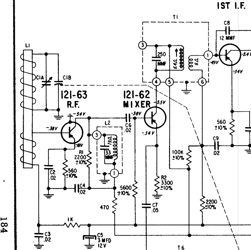
I have a bunch of truly vintage (1950s) Zenith Royal 500 portable radios, and some models use a RF amplifier, but with a standard 2 section variable capacitor. The model numbers begin with “8”, such as 8AT40Z2 (see attached schematic). These have the usual tuning capacitor across the loopstick to tune the input of the RF amp. After the RF amp, the collector load is another tuned circuit, L2, which is tuned to the middle of the AM band. This would give a peak in the middle of the band. But the designer put R1, a 2200 ohm resistor across the tuned circuit. The resistor changes the sharp peak to a flat plateau that has less amplitude, but it has about the same amplitude across the whole AM band – it has been changed into a broadband amplifier.
So the radio’s selectivity is given by the tuned loopstick, and the sensitivity is increased by the RF amplifier. Also, the transistor’s base bias is supplied through the 1k next to C3 which is connected to the AVC line. Strong signals cause the AVC line to reduce the gain of the RF and IF amps, which keeps the volume the same.
Here is where you can find this and other Zenith radio schematics:
http://www.transistor-repairs.com/schematics.html