default

2016-10-18 FM Transmitter Uses Power MOSFET

I watched this YouTube video where the author shows his FM transmitter using a big 60 volt power MOSFET. He also shows a very readable photo of the schematic. The video was made several years ago in 2012.

He is powering this transmitter by connecting it to eleven 9 volt batteries in series, totalling 99 volts. The power MOSFET he is using is rated for only 60 volts, which is not a good situation. For any LC oscillator, the power supply should never be more than half the maximum collector voltage rating of the transistor, in this case, 30 volts. The reason why this circuit has not failed is that the circuit has a 5k, 10 watt resistor in series with the negative supply. He says that it gets warm. If the 5k is connected directly across 99 volts, the maximum current would be 20 milliamps, so the current must be less than that. This circuit is wasting a large voltage (and therefore a lot of power) across the resistor. My guess is more than 50 volts, but he doesn’t say how much voltage is across the resistor. This is wasting more than half the battery power heating the resistor. The battery voltage should be much less, and this resistor should be much lower, only a few hundred ohms.

I have built quite a few of these 1 transistor FM transmitters, and I’m very familiar with the coils and capacitor values. I have a really handy tool called a FET dipmeter. It’s easy to find the frequency of resonance with this. I wound some wire around a AA battery just like he said and showed in the video. I connected a 30 pF capacitor across it and found the resonant frequency and it was between 45 and 50 MHz. I am reasonably certain that his transmitter is oscillating at about that frequency and what he is hearing on the FM radio is the second harmonic, between 90 and 100 MHz.

In order to get the fundamental frequency of his transmitter up to the FM band, the coil must be much smaller. The coil’s diameter should be smaller than a pencil, about 5 mm or 0.2 inches. And the number of turns should be reduced, 3 or 4 at most. The tuning capacitor he is using should have a maximum of 30 pF — he said that is the capacitor’s minimum. He could connect a 47 pF capacitor in series with the tuning capacitor to reduce the total capacitance.

I think it will be difficult for the MOSFET to get up to the frequency in the FM band. The typical power MOSFET has high internal capacitances, and these will change depending on the voltage. So the frequency will depend too much on the MOSFET, and as the battery voltage changes, so will the frequency.

I enjoyed watching this video, it is interesting that a power MOSFET can get up to fifty MHz. But I think it would be better to use a small transistor such as a 2N3904 for this project – it should be powerful enough to hear for a hundred feet (30 meters).

default

2016-10-04 Joule Thief Powers Field Strength Meter

There are many circuits that are used infrequently that are powered by the usual 9 volt battery. One of these happens to be a field strength meter (FSM), which is used for detecting the power output of a transmitter such as the one a radio amateur uses. Some FSMs are very simple and use no battery. I chose this circuit because it uses the 9 volt battery, takes very little current, and does not care if the power supply is noisy and unregulated. And it is turned on only for short periods, very intermittently.

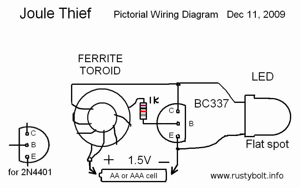
A standard Joule Thief (pic in this link must be clicked more than once) is used with a few modifications . It is powered by a single 1.5 volt AA or AAA cell. This has the advantages that it is smaller and much cheaper than a 9V battery.

The first modification is the coil. Since the voltage will be higher, the coil will have a different number of turns for each winding. The typical Joule Thief might have ten turns for each winding. This will be changed so that the main winding for the LED will have 16 turns and the feedback winding to the resistor will have 8 turns or half as many turns as the main winding. This allows the LED voltage to be twice as high without exceeding the transistor’s base voltage.

The Joule Thief’s pulsating output has to be rectified and filtered. We replace the LED with a 1N4148 diode. The anode (the end without the band) is connected to the collector and coil. But the cathode (banded end) is connected to the positive lead of a 22 uF, 16 volt electrolytic capacitor. The negative lead of the capacitor is connected to the negative of the battery. The diode rectifies the pulses and the 22 uF filters out most of the pulses, so we now have unregulated DC.

The next change is to connect a zener diode across the capacitor. We connect the cathode (band end) of the zener to the capacitor’s positive lead. We choose a 6.8 volt zener diode, and connect a red LED (2 volts) in series with the zener to get a total of 8.8 volts. You could also use a 6.2 volt zener and a 3.2 volt blue or white LED. The cathode (flat spot) of the LED goes to common negative, like it was in the original Joule Thief. The anode of the LED is connected to the anode of the zener diode. You can use any NPN transistor in place of the zener. Connect the emitter to the capacitor’s positive, and the base and collector together and to the common negative. The emitter to base junction will act like a zener. But the voltage may be anywhere from 6 to 9 volts, so measure it to see if it’s okay. If you use a transistor for this, it may have its current gain severely damaged, so I recommend cutting the leads off and putting it in the trash.

The Joule Thief uses a 1k resistor, but the resistor can be increased to save power. It can be 2.2k or maybe more. First let’s do a few calculations. The standard Joule Thief puts out about 20 milliamps at 3.3 volts to the LED. That’s about 66 milliwatts. The FSM uses about 1 mA for the 10k trimpot, and 0.25 mA for the FET and meter. That equals about 1.25 mA max at 9 volts, or about 11 milliwatts total. So if we set the Joule Thief to generate 30 milliwatts total, we can have 11 mW for the FSM and 19 mW for the zener and LED, to show that the power is on. The resistor depends on the current gain of the transistor, which may vary widely.

The FSM is used during transmission, not while receiving. If you have it on during receiving, you might hear some noise at some frequencies while tuning. I think this might be a good warning indicator that you left the FSM on. However if you use a pushbutton switch or you just don’t want to hear the noise, connect a ceramic capacitor, such as a 0.01 uF (“103”) across the 22 uF. If you still hear noise, use some ferrite beads on the leads from the battery holder, and the leads from the Joule Thief to the FSM. If the whole circuit is inside of an aluminum enclosure then it should stop the RF noise from getting out.

Another change to the FSM. The on/off switch should be connected between the AA or AAA cell and the Joule Thief.

I have used another circuit similar to this to power a cheap DMM, and it does the job okay. It had a regulator that turned down the circuit when demand went down. This Joule Thief circuit draws the same battery current no matter what the load is. But the FSM is used very infrequently so it shouldn’t make any difference in the battery life. If this circuit is used for frequently used equipment, then a rechargeable battery can be used. If it will sit for long periods without use, the Eneloop rechargeable cells will hold their charge for a year or more. Since rechargeables put out 1.25 volt instead of 1.5 volt, the Joule Thief’s resistor might have to be lowered a bit.

default

2016-10-03 Ordered Thru Hole Transistors

I went online a few days ago and looked for some odd RF transistors, but instead I was shocked.  Almost all of the parts I’ve been using are through hole parts, like transistors in a TO-92 package with wire leads.  I looked at a few distributors such as Mouser, Avnet, Arrow, Digikey, Newark.  I found that most of them are not stocking transistors with wire leads, they stock only the SOT-23 surface mount packages.  I tried to find the J310, but the only thing at Mouser was the MMBTJ310, which is the same as the J310 but in that teeny tiny package with short tiny tabs.  The store I found was Futurlec, and the prices were higher.  I just figure that soon the only parts we can buy will be surface mount parts.

So I ordered from Mouser a tape reel of a thousand 2N3904s, which used to be very common, but now they have none in stock.  They are back ordered and will take 6 weeks.  That’s half way through November.  But by ordering a thousand, the price is less than 4 cents apiece, so they’re not that expensive.  Besides they may stop selling them, and then I’ll have to buy from eBay, where the prices might be 5 or more times higher.
Update – I checked eBay and found one seller who must be the absolute worst ripoff when it comes to parts. The seller wants $24.99 for a single (very common) transistor, which costs less than ten cents from other sellers.

I just received an order update from Mouser, says some capacitors I ordered won’t be in stock until the middle of January. Every through hole part seems to be a vanishing or extinct species. Bummer!

Update Oct 14 – I searched for MPSA13 which is a common Darlington NPN transistor and I couldn’t find any available at most distributors except Mouser, which wanted $0.18 each. Wow, that’s a lot. I finally found them at Futurlec.com for $0.06 apiece, 1/3 of what Mouser wanted. I bought a bunch, so they’ll be there in the future. No future plans means no parts!

default

2016-09-29 FM Quality Stereo Tx

When I googled I found a ‘stereo input’ FM transmitter. Most of the FM ‘bugs’ on the web and YouTube have a microphone.  The circuit I linked to has left and right inputs, but mixes them to make a monophonic (not stereo) signal. 

After looking at the schematic I noticed a mistake, so I thought it would be wise to let others know. I also explain some important things to know before building one of these. These issues can cause problems for the builder if he is not aware of them when putting it on the air.

The value of C3 is shown as .001 uF, but it should be .1 uF or more. This will prevent the transmitter from sounding tinny.

The value of C5 is shown as .01 uF but it should be .001 uF or 1000 pF (‘102’ ceramic disk). This also will stop C5 from affecting the quality of the sound.

Peter found another mistake. It says:

L4: 5 turns of 28 SWG wire on an intermediate-frequency transmitter (IFT) ferrite core

It should read:

L4: 5 turns of 28 SWG wire on an intermediate-frequency transformer (IFT) ferrite core

Thank you, Peter.

This L4 is used as an RF choke, to keep the radio frequencies from going back into the positive supply. It can be replaced with any RF choke, I think any value of 4.7 to 22 microhenrys should do the job. If you have a spare IFT, you could use it, but you have to take it apart and wind the wire around the core. I think 28 SWG is equal to 27 or 26 AWG, but you should be able to find a SWG to AWG to metric wire conversion table on the ‘net. The wire size is not critical.

Some important issues that might cause problems
This transmitter puts out enough power to make it a bit difficult to get it to operate properly. It may take some reading, but this is important to know.

Build this on a piece of PC board, not a breadboard. And keep all of the leads and wires short and unmovable. If they move, the frequency will change. Unstable wiring, especially the coil, will cause microphonics.

The 22 pF tuning cap VC1 sets the frequency. The schematic shows it as the only capacitor across the L1. The problem is that this makes it very difficult to tune to the right frequency because the capacitor will be very touchy. Just a slight adjustment will change the frequency a very large amount. Instead of this 22 pF adjustable, it should be replaced with a 15 pF silver mica or ceramic capacitor, of the type NP0 or C0G. Then connect a 1 to 5 pF adjustable capacitor in parallel (across) the 15 pF. This will be much less difficult to tune. Additional tuning can be done by squeezing or spreading the coil.

Also, it shows T1 as a BF494. This is hard to find, but can be replaced with a BC548, BC547, 2N3904, or other similar transistor.

It shows R4 and VR2 as the Power Control. The problem is that every time you change VR2, it will change the frequency. So then you have to go back and readjust VC1. It is best to replace both R4 and VR2 with a single resistor of 220 or 330 ohms. It could be higher for less power.

The antenna is tuned by VC2, another 22 pF adjustable capacitor. The problem is you need some way to tell when it is tuned to optimum output. You can’t measure the supply current, because it doesn’t ‘peak’ when the power out is optimized. What is needed is a field strength meter. This one is very simple, but could be even simpler. There is no need for the 47k variable potentiometer, it can be replaced by a 1k to 10k resistor and the DMM connected across it and the 470 pF capacitor.

This FM transmitter may not be legal in some countries because it may exceed the maximum power allowed. After building the first transistor’s circuit but before adding L2 and the output transistor, I would try putting it on the air. I have found that just the first transistor can usually be heard 50 to 100 yards or meters. If that’s good enough, then don’t build the last power output stage. Don’t add L2 and the second transistor’s circuit.  Instead of 9 volts use 5 or 6 volts for the supply.  And no antenna.  The first transistor circuit should be strong enough to receive at 50 meters, with just the radiation from the coil.

default

2016-09-28 Battery keeps Joule Thief Lit

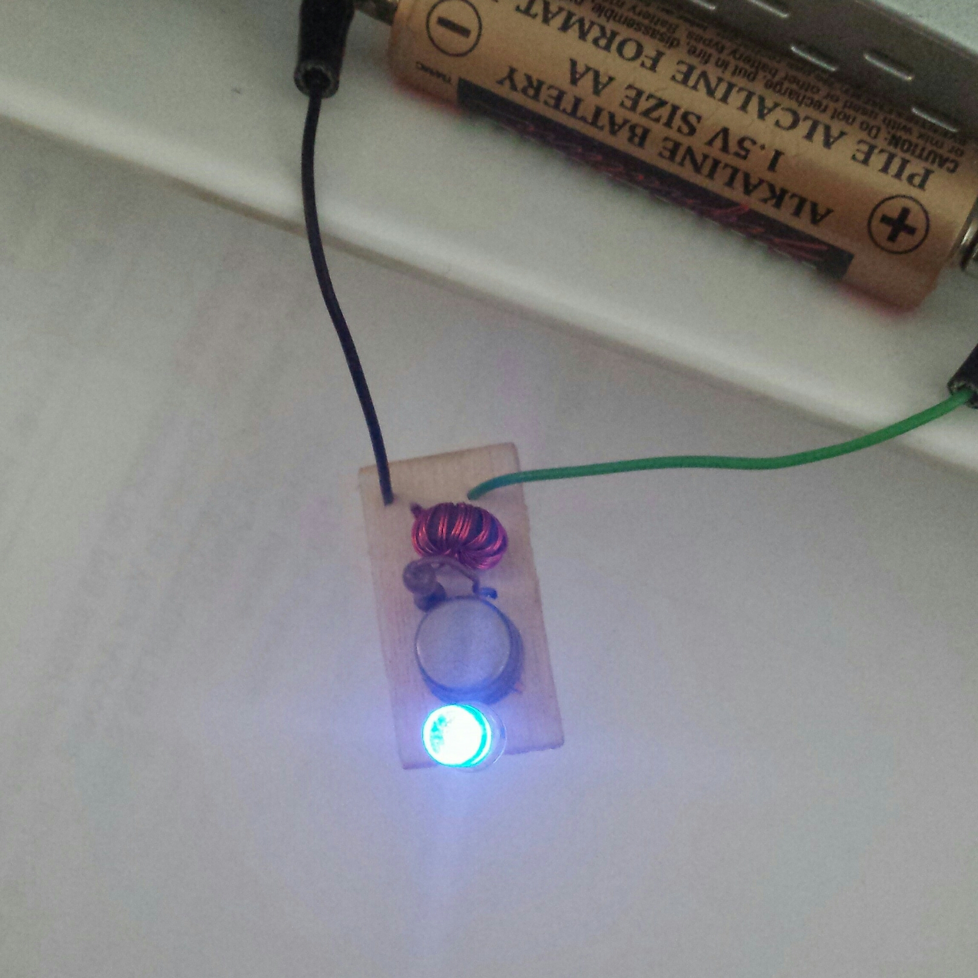
I put this AA cell, which measured 1.3 volts – ‘dead’ – on one of my germanium Joule Thiefs more than a week ago. It was glowing very brightly for a few days. For the last few days, it has been weakly glowing, and the Kirkland AA cell is still hanging in there, even though its voltage is only 0.19 volts. This JT is milking the last few millivolts out of the cell, even though it’s far below the cutoff point for a silicon JT.

The weather has been hot, and the cells, especially AA cells, have been leaking electrolyte and corroding contacts. I had one JT with a battery holder go dead. I checked and found that the juice had wicked up the strands of wire in the leads, and the copper wires were corroded green and crumbling when it was moved. Yuck. The juice also eats away the chrome plating on the little magnets I used to hold the leads to the cells.

image

Update Oct. 5th evening – The LED is still glowing. This battery isn’t dying easily! It finally went out the next day.

default

2016-09-20 tbd

from a comment I added to this YouTube video
https://youtu.be/GCh2LVHUavQ

The main difference between a power transformer and an audio transformer is the way the E and I laminations of the core are arranged. The power transformer has an E on the left and I on the right of the first layer, then an I on the left and an E on the right of the second layer and so on, so alternating layers have E or I on the left. This makes the core almost like a solid block and the transformer is optimized for 60 or 50 Hz.

The audio transformer has all E’s bundled together, and all I’s bundled together, and they are assembled and held together with a piece of thick paper between the E’s and I’s. This air gap created by the paper optimizes the transformer for a wide band of audio frequencies.

You should try to take one of the power transformers apart. The first E and I laminations is very hard to get out, but after that it’s easier. A rubber mallet helps a lot but don’t break the windings. Then you can put it back together with the paper and now you have a wider band transformer. But the way you have been doing it works, for noncritical use.

The big MOT has too much core loss. Save it to make a spot welder. 🙂
Great video.

default

2016-09-19 Soldering Iron Shutoff Timer

Read update at the end first.

I was searching for some regenerative receiver schematics and looked at some other circuits. Google says similar images, but it doesn’t know anything about the purpose of the image, it just knows that it has lines connecting different symbols, and even then I’m not sure if it even knows that. It may be just some mathematical algorithm. Someday I should find a bloody murder photo and see what other photos it thinks are similar.

One of the images it showed was a soldering iron shutoff timer. The specs called for several tens of minutes delay before shutting off. The schematic was somewhat complicated, it used a CD4060 chip that has an RC oscillator and divider to give long delays. I thought, why bother? The oscillator is not very accurate because it uses R and C, and even a 555 timer chip can be just as accurate. I could use a low leakage tantalum capacitor and a megohm resistor and get several minutes of delay. I know this because I built a timer using a 555, to control the exposure time of a photo enlarger. And that was when they didn’t have CMOS 555 chips. Today, a CMOS 555 draws almost no current from the RC timer circuit. So the 555 is a simple, cheap solution.

Later I got to thinking about how it could be done mechanically. People are not impressed by a box with electronic parts that does something. But when they see a mechanical device that they can understand, then they are impressed. Wow, this is a mechanical genius! Remember those Halloween boxes? You turned on a switch, and a second later a trap door opens up and a hand slides out and turns off the switch, and goes back inside! Cool! People actually bought these simple little things.

All sorts of ideas rushed through my head. I thought about a simple motor with a gearhead that turned slowly, with a spool on the shaft and a few feet of thread. After many minutes when the thread was all wound up, it would pull the switch off. I scrapped a microwave oven and recovered the turntable motor, which has a speed of a few RPM. If I could get a slower motor, I wouldn’t need that much string.

What has a slower motor? How about a light timer, to turn the lights on at the same time every day? Then bingo! It hit me that this would work perfectly for the timer. Just set the pins for an on time of a half hour, and plug the soldering iron into it. But the problem is that it turns on at the same time every day. What I have to do is put a relay between the timer and the wall power, so that when the timer turns off, it also turns off its own power. In order to start it, I would have to turn the dial around until the timer’s switch turns on. Then after a half hour, it shuts down everything including itself.

I guess this is the simplest and cheapest way to build a timer, and it’s mechanical but totally unimpressive to others. These electromechanical timers are only a few dollars at the discount stores. A 120 VAC relay might be bought for several dollars surplus. If the contacts are rated for 15 amps or more, then it could be used for a clothes iron or other appliance like a coffee pot.

I’m going to look online for something that might do this without having to build one.

Update – I found just what I was looking for. I’m glad I shopped around. Amazon and others wanted $20 or more, I got it on eBay for $11 and free shipping. Search for FD60MC.

http://m.outletpc.com/vc8478-2-prong-12-hour-appliance-shutdown-timer.html

If these links are not working, then do a search for appliance shutdown timer.

default

2016-09-16 Soldering With Sunlight

I was considering what I would do if the electricity went off and I needed to solder something.  I was on YouTube and I watched a guy make a battery operated soldering iron from copper wire, part of a telescoping antenna, wood, fiberglass sleeve tubing, some 0.2mm nichrome wire, and battery and holder. The video was speeded up so I would have to stop it very often to catch everything.

I went on eBay and Amazon and found 0.2mm nichrome wire and ordered a 10 m roll for a few dollars.  I then went looking for battery powered soldering irons and found several, which looked very similar and were probably all made by the same manufacturer in China.  The least expensive were all around $17.00 US.  Shockingly, though, some sellers were pricing it far lower, with ridiculously high shipping charge, adding up to even more.

I found a few soldering ‘torches’ that ran off butane or lighter fuel.  They weren’t cheap, but they don’t depend on any electricity.  Then I found several irons which plug into the USB port for power.  They are 5 volts and 8 watts, which comes to about 1.6 amps.  That’s more than a laptop port (1/2 amp) but can be powered from a power bank.  I read a few reviews while I was looking around, and found that many were not favorable.  Some adverts mentioned using the iron for soldering car wiring, but with 18 gauge or thicker wire, an 8 watt iron just doesn’t have enough heat to melt the solder.  It should work with 24 AWG and smaller and with small joints on PC boards, so I ordered 2 of the USB irons for less than 5 dollars each.

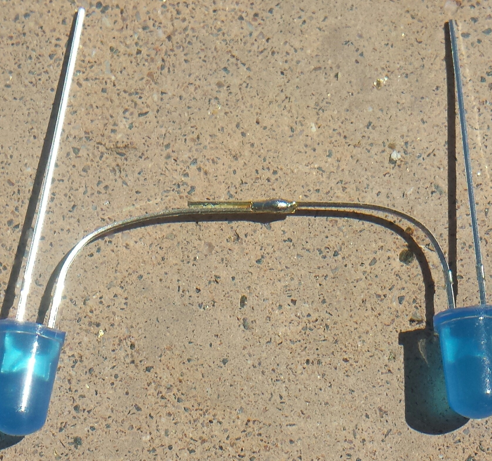
While I’m waiting for those to arrive (a few weeks from Hong Kong), I thought up another experiment.  I got two LEDs, solder, a 75 mm glass magnifying lens, and dark sunglasses.  I went outside and laid the LED leads on the concrete, in bright sunlight, and heated them with the lens, and finally got the solder to flow.  It took too long, the lens wasn’t getting it hot enough, fast enough.  The solder joint came out looking okay, but it could have been quicker and larger if the lens was larger.  I’m satisfied that my experiment was successful for the most part.

image

I have a plastic fresnel lens the size of a sheet of paper, which should have a lot more heat than the glass lens.  Long ago I noticed that it was much easier to burn the black letters than the white newspaper, so the shiny metal may be reflecting a lot of the heat.  And I really need darker sunglasses.  😎

I have a hundred watt monster soldering iron that runs of 28 volts, and it’s connected to a 28 volt DC power supply that plugs into the wall. I could power it from 2 car batteries in series. If I could get two car batteries — I have only one car. I suppose I could connect it to a single battery, but it would only be 25 watts, and it might not get hot enough to do the job. And it’s really too big for any electronic equipment.

default

2016-09-15 Digital Thermometer Dies

The LCD on my digital thermometer faded away, so I knew that it needed to have the single AAA cell replaced. I bought the indoor/outdoor thermometer probably more than two decades ago from Radio Shack. This time, I removed the AAA cell and I had marked it as installed in Nov of 2005, so it has been working with this cell for more than ten years.

I guess I can’t complain. Most of these come with one or two button cells, so they last for a year or two before needing replacement. There is plenty of room for the AAA cell, there is no need to reduce the size of the battery. The alkaline button cells may be cheaper than a AAA cell, but I doubt they are cheaper than a zinc carbon cell, which should last five years or more.

The LCD draws very little current, tens of microamps. But the thermal sensors have to have enough current to measure their resistance. Fortunately the temperature changes very slowly, so a measurement can be taken for a small fraction of a second every several tens of seconds, which means the duty cycle might be less than 1 percent, and the average current is very low. The digital circuit itself is doing very little, so it also can have a very low duty cycle.

This same effect is what allows a crystal controlled clock movement to tick off the seconds for more than a year using a single AA cell. Intermittent operation makes the duty cycle very low.

default

2016-09-10 tbd

I was coming back from lunch, walking through the parking lot of the shopping center across 17th St from the college. I saw Pat Ewing also walking several rows away. We were both headed for the crosswalk at the front entrance of Santa Ana College.

All of a sudden this pickup pulls into the parking lot entrance, and a police car was right behind him, lights flashing, and both came to a stop. The cop got out of the car, crouched behind his door, and drew his gun and pointed at the truck.

I rushed behind a car, and peeked through the widows to see what was going on. I noticed that Pat also wasn’t visible. I saw the guy in the trick roll down his window and put both hands out the window. I decided that I would try to go closer to the crosswalk, and get away from the action. I finally distanced myself from the scene before I looked back and saw the cop take the guy into custody.

On another occasion, I was walking outside on a chilly morning, and came up beside Pat. She said, “It’s cold, you should be wearing a jacket.”
I said, “I don’t think it’s that cold. When I was in Minneapolis, now that was cold!”
She told me that she grew up in Saskatoon, Canada, far north of Minneapolis.
“Well, then you should know what cold really is! This is nothing compared to that!” I said.
But she said she had lived here so long that she had become accustomed to the mild weather here, and she just thought it was cold this morning.

Pat Ewing was the switchboard operator for the College and when they replaced the switchboard with dial phones, she worked in Admissions as a clerk. She retired several years before I did.

Miscellaneous photos

image

More
image

© RustyBolt.Info/wordpress
CyberChimps