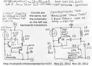
 I saw this Youtube video of a schematic of a two transistor “Joule Thief” by Sanjev21 (update Nov 27 – I notice that this video has been removed – see note at end). This circuit is very similar to the one that I have already blogged.
The problem that I see with the original, and also with this one (see the left schematic in the attached photo) is that the collectors and emitters of both of the transistors are swapped. The collector of a NPN transistor (2N2222A) should always be more positive than the emitter; here it is more negative. Likewise, the collector of a PNP transistor (BC557) should always be more negative than the emitter; here it is more positive. In both cases the backwards transistor normally does not work and the circuit is non-functional.
In the schematic on the right, I show a typical two transistor “Joule Thief” that cane be found on many websites. The transistors are connected to the correct polarities and the circuit will work, and light the LED. The circuit on the left, which is the one seen in the video, is incorrect and will not work.
Note- I was not the only viewer who noticed the mistake he made. Perhaps he decided that others were correct – there was a mistake in his schematic – and removed the video.


