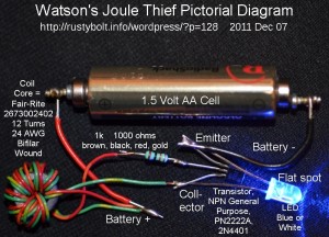
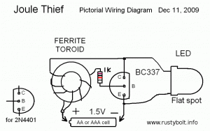
 This is a pictorial diagram of a Joule Thief (JT). It is meant to give a simple visual guide to those who wish to assemble their own JT. I’m also adding sort of a Joule Thief FAQ to explain in simple terms what a JT is.
JT – WHAT IS IT? A conventional Joule Thief is a simple, easy to build a circuit that consists of the following components: (refer to the accompanying drawing)
1. A battery (it’s at the bottom), typically a single 1.5V AA or AAA cell, to supply power to the JT circuit. The battery voltage must be less than the voltage that lights the LED (which is 2V for red, 2 2 to 2.5 volts for orange and yellow, around 2.7 volts for green, and 3.2 volts or more for blue and white LEDs).
2. A LED (Light Emitting Diode) (it’s on the right), typically a white or blue LED, but other visible colors will also work. The forward voltage of a white or blue LED is about 3.2V, but the LED will begin to light up below 3 volts.
3. A transistor (it’s in the middle) to switch the current to the coil (inductor) on and off rapidly. This transistor is typically NPN, and some common types are the 2N4401, PN2222A, BC337-25, 2N3904, BC547. The last two types are not capable of lighting the LED to full brightness. “But they work,” says the neophyte experimenter. The JT’s maximum current exceeds their maximum rating, and the result is excessive losses and poor efficiency. A good choice for a transistor is one that has low Vce(sat) at low voltage, high gain, and can handle several hundred milliamps of current. See the transistor’s datasheet for more information.
4. The coil or inductor (it’s on the left). This has two windings, the primary or main winding, and the feedback winding. The primary winding is the only winding needed to light the LED; the feedback winding is there only to keep the circuit running and to switch the transistor on and off. Therefore, the coil does not transform the voltage, which is actually increased by the counter EMF of the primary winding. The coil/inductor is typically wound on a toroid core, which looks like a tiny doughnut. Both windings are typically wound at the same time, which is called bifilar wound. In the pictorial, it shows two separate windings, wound so that the coil looks like it is tapped in the center, where the battery’s positive connects to it (for clarity, only six turns are shown; a typical coil will have 12 or more turns). When a core is wound with both windings at the same time, and the end of the first winding is connected to the start of the second winding, it is the same as the winding shown with the tap in the center. Other forms of coils will also work, including an air core coil.
5. The resistor (colored rectangle to left of transistor), typically 1000 ohms or 1k (brown, black, red, gold stripes). This limits the base bias current which flows from the battery positive through the feedback winding to the transistor’s base. Most common is the 1/4 watt resistor, but 1/2 watt will work, it just takes up more room.
Optionally, the battery is bypassed with an electrolytic capacitor typically 10 or more microfarads (not shown). It is considered best practice to include this even though the circuit will work without it. Some JT circuits add a small capacitor, typically a few hundred to 1000 picofarads across the resistor. This seems to help increase the brightness and efficiency of the JT.
These five components are what were in the original circuit named the Joule Thief. Some experimenters incorrectly give the “Joule Thief” name to other circuits that perform a similar function, but they are not a true JT.
Back to experimenting…


it is very nice ,now i can amaze freinds with this jt circuit
Well, I can help you make a JT, but I cannot help you with your friends. Perhaps if you choose young and impressionable people, they may be amazed. I bought some multicolor flashing LEDs, and they look very impressive when I put them on a JT.