I my previous blog I determined that the Joule Thief flasher was not suitable as a flasher, but it was working well as a modified Joule Thief, with better efficiency than a conventional JT. I gave the schematic of the circuit, but I have made many modifications, so I decided to build a second one so that I can get another separate and independent idea of what this circuit can do.
I tack soldered the circuit together so I could take a photo of it and show how it was wired. It’s a simple circuit, not much more complicated than a conventional JT, with the exception of a capacitor added in series with the feedback winding.
The circuit is the same as the original, a PN2222A with a base bias resistor of 3.9k and the capacitor is 100 pF. The coil consists of a Fair-Rite 26730042402 core with 16 inches of 28 AWG trifilar wound on it. Two of the windings are connected in parallel for the primary winding. The inductance measured 750 microhenrys. The LED is a white LED, and the green thing below it is just holds the 1 ohm current sensing resistor and makes it easy to connect to it.
I connected a variable capacitor to the circuit and adjusted it for maximum LED current. I removed it and it measured 96 pF, which was so close that I replaced it with a 100 pF disk capacitor.
Results
For my second circuit, the supply current at 1.5V measured 95 milliamps and the frequency was 410 kHz. The LED current measured 16.1 milliamps. The LED current was close to the original but the supply current was almost twice that of the original. This was much less efficient than the original. But the original used a coil with 262 uH, and this coil is nearly three times that much: 750 uH. This may be the reason why the efficiency is lower. I would say most of the difference in the circuit is in the coil, since the rest of the circuit is about the same. I may remove some turns from the coil to see if it helps increase the efficiency.
Big Change For The Better With Fewer Turns
I removed 6 inches of wire, leaving about 10 inches. Each winding measured 263 microhenrys. I reconnected the windings and fired it up. To my pleasant surprise, the LED current remained at 16 milliamps but the supply current had gone down, to a bit below 50 milliamps. The frequency was 494 kHz, near the first’s frequency.
So now this second modified Joule Thief was giving me the same efficiency as the first one, and slightly more LED current with about the same supply current. The capacitor was still 100 pF. At 494 kHz, the reactance of this capacitor is about 3222 ohms.
The 16.1 mA LED current is at the bottom end of what I would like it to be, which is 20 mA. I decreased the resistance from 3.9k to 3.3k, and the LED current went up to 17.8 mA, which is a very comfortable value, almost 20 mA, and it has nearly the same light output. The frequency then went up to 550 kHz, right at the bottom of the AM broadcast band. But to keep everything at the same point, I changed the resistance back to 3.9k so that any further changes would be relative to both the first one and this modified JT.
A Third Modified JT
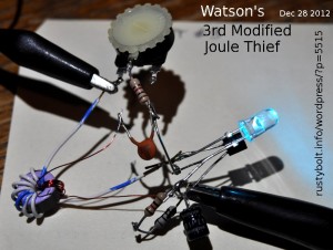
Just to confirm what I’ve done before is not a fluke, I built a third modified JT. This one used the same Fair-Rite 2673002402 core but the turns were less, just enough to give a bit more than 100 uH. Both windings were 8 turns, one winding of 24 AWG telephone wire (white/blue) and the feedback winding was 30 AWG enameled magnet wire.
I used a PN2222A again and the LED was a blue-green with a voltage drop of about 2.9 volts. To make up for the difference between 2.9V and the usual 3.2 volts of the typical white LED, I put two resistors in series with the LED to ground, one resistor was 10 ohms so I could measure the current. I found that these resistors caused the LED to be dimmer, so I put a 47 uF capacitor across them to allow the peak current pulses to flow unimpeded through the LED.
I put a 10k pot in series with a 1k resistor so I could adjust the amount of base bias current. As previously. I put a variable capacitor in place of the ceramic disk, and adjusted it until I got a broad peak, It measured 112 pF, so I again removed it and used a 100 pF ceramic disk capacitor.
The performance is very close to the other two. With the pot adjusted for 50 mA supply current at 1.5V, I got 15.6 milliamps LED current, and the frequency was 556 kHz. The performance was very similar to the two previous modified JTs and the efficiency calculated to about 68 percent.
I’m satisfied that the circuit is easily replicated and the performance is consistent with the same part values.


[…] I’m building a second one, so read my blog about it here. […]
I’m not sure if this is a question the commenter is asking, or what.