


I built this special Joule Thief a while ago, and I don’t remember if I wrote a blog about it.
To enlarge, click more than once.
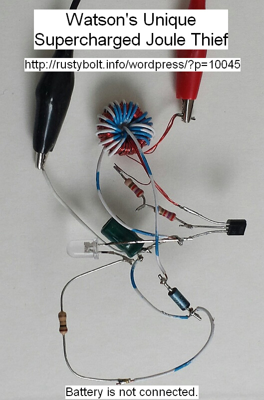
I wound the two normal windings on the toroid core, then I wound a third winding of 20 turns for driving the LED. But instead of driving the LED directly from the transistor, I connected one of the 3rd winding leads to negative and the other lead to the anode of a 1N5817 Schottky diode. I connected the cathode of this diode to the positive of a 100 uF ‘lytic capacitor and connected its negative to the battery negative. In other words, the pulses from this winding are being rectified and filtered to DC. One important thing to remember is that this winding may give higher LED current when connected in one direction, so it’s best to try both directions and use the one with the highest LED current (see note).
This DC is then connected directly to the LED. A 1 ohm resistor is between the LED cathode and the negative to allow the LED current to be measured: 1 millivolt equals 1 milliamp.
The rest of the circuit is a conventional JT, but instead of a 1k resistor, I used two 27k resistors in series, totaling 54k. The transistor was a BC337-25. It used a standard 5mm white LED.
The battery current measured about 23 mA, but when I put a short across the meter leads, I could see the LED get brighter, so I estimate the actual battery current is more like 27 mA. The meter read 8 millivolts across the 1 ohm resistor, so there are 8 milliamps through the LED. I calculated an efficiency of about 64 percent, which is a reasonable value for a Joule Thief.
Note: Some experimenters try to solve this by using a diode bridge rectifier. but the bridge has two diode drops totaling 1.2 to 1.6 volts, which is up to half the power sent to the LED being wasted in the diodes as heat. Obviously this is not a good idea. Less diodes is best. Also using a Schottky diode with low voltage drop wastes less power.


Do you have a schematic for this? I’ve been experimenting with this circuit:
http://talkingelectronics.com/projects/30%20LED%20Projects/30%20LED%20Projects.html#2
It is very efficient drawing about 27mA (amp meter in series with the circuit) and the toroid seems to be very forgiving as I currently have a 2-winding ferrite bead (VHF choke) in mine with a 1k resistor. It will power a high power LED for a few days off of a rechargeable battery. I’m updating the circuit to add a solar cell and light sensor and make laden jar solar lights.
There is no schematic because the wiring diagram is right there on the picture, along with the explanations in the text. The BC337-25 transistor pinout is from top to bottom, C, B, E. The diode is a 1N5817 Schottky diode. The LED lead is very close to the cap lead but does not connect to it; it is only connected to the 1 ohm current monitoring resistor, which is optional. I looked at the colors of the two resistors and they look like 2.7k, not 27k. It would be best to use one 1k in series with a 100k pot to adjust the brightness.
I used a 1/2 inch toroid. Use whatever you have and add 20 turns of fine wire to it for the third winding. It’s an experimental ‘breadboard’ circuit so experiment a bit.
As for the TE circuits, Colin hasn’t been receptive to my inquiries. But I think the bobbin and fine wire he used had too much DC resistance for good efficiency. A normal Joule Thief with a 1k resistor will draw about 60 to 90 mA from a fresh battery. Adding the 100k pot will let you adjust it to much lower current. If you use a high resistance, the JT will give better performance if you connect a 1000 pF capacitor in parallel.