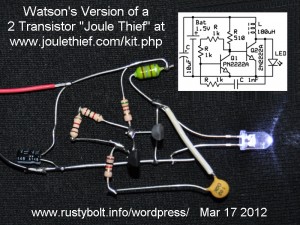
 I saw this schematic for a kit that was sold at one time. It uses 2 transistors, and the author claimed that it was 70 percent efficient. I wanted to build one to see what my results would be. Technically it’s not a true Joule thief, which uses only one transistor and has a two winding coil. The LED is so-so bright, my guess being a current of less than 10 mA.
I made a few changes to the original schematic. I changed Q1’s collector resistor from 1k to 510 ohms. The voltage across this resistor when Q1 is off is only 0.9 volts, and the current to the base of Q2 is only 0.9 milliamps. The Q2 collector current has to be as much as 200 milliamps, so Q2 must use all of its current gain, and Q2 may not turn fully on, its collector voltage may not drop to a small fraction of a volt like it should. By reducing the resistor to 510 ohms, it doubles the current to Q2’s base, and makes it turn fully on, like a switch.
I used a 180 microhenry choke for the coil, mainly because I have dozens in my junkbox (LOL), but also because the small chokes have very fine wire, and their DC resistance can be too high. The 180 μH choke has 1 ohm resistance, which is less than the 470 μH called for, but 1 ohm is still higher than it should be. To keep losses low, the DC resistance should be less than 1/4 ohm. That’s easy to do if a reasonably high permeability toroid is used. But hey, when you have a bunch of lemons you make lemonade, so I used one of those dozens of 180 μH chokes.
I changed the two 1k resistors between Q1 base and collector to a 10k trimpot. When I adjusted the trimpot to more than 3.3k, the supply current went up and the LED got slightly dimmer. The on/off time of Q2 was changing so that Q2 was turning on longer than it was off, which was wasting power heating just the transistor and choke instead of going to the LED. My guesstimate is the range of values for this resistor should be in the 3.3k or less, down to 2.0k, but it depends on how much current gain Q1 has.
With the two 1k resistors, the supply current was about 70 milliamps, and I measured the frequency at 85kHz.
I’m working on getting the circuit optimized, and I’ll get to the measurements as soon as I get a better feel for how this circuit performs. Update 6 mos later – I conclude that since my Supercharged JT is simpler and more efficient, there is no justificaton for trying to obtain better performance from this circuit.


