


A question a Youtuber brought up made me think about going to the opposite extreme from the one I normally pursue: trying to get a Joule Thief to run at very low power. Normally I would try to maximize both the light output and efficiency.
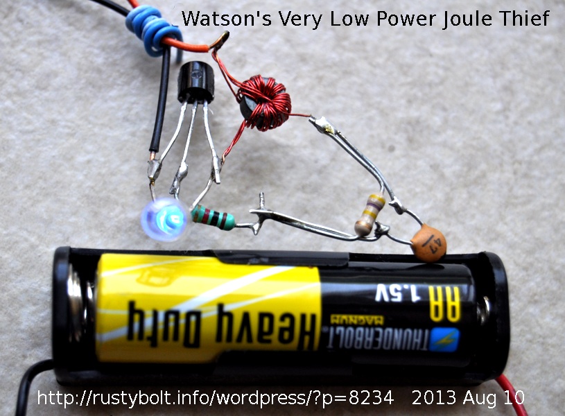 I started out with a run-of-the-mill Joule Thief having a coil, a BC337-25 transistor, a 1k resistor and a blue LED. The coil was a T231212T core only a quarter of an inch (6.4 mm) O.D., with four windings of 7 inch lengths of 30 AWG enameled wire wound quadrifilar, with three of the four windings connected in parallel for the primary winding. The blue LED lit up very brightly, and the supply current was the typical 60 or so milliamps. In order to reduce the LED brightness and the supply current, I chose to increase the 1k resistor. I added a 100k pot in series to allow me to adjust the brightness. As I adjusted this pot from 0 to 100k, the brightness dropped a lot, but the LED was still putting out quite a bit of light.
I decided I would try a higher resistance, so I put a 51k in series with the pot, and as I adjusted the pot to a resistance above 110k, the LED went dark. Well, I figured that the problem was being caused by the loss of drive from the feedback winding, which also had to go through this 110k or more resistor. I clipped a small capacitor across the resistors so that it was in parallel with the total 151k of the pot and 51k resistor, but it was still in series with the 1k resistor. The capacitor was a .0047 uF or 4.7 nF. The LED lit up again, but not brightly. So now that I had the LED working, I could again increase the total resistance, so I put a 470k in series with the 150k and put the capacitor across the 470k and 150k, but leaving the 1k resistor still in series. The LED still stayed lit, so I measured the supply current, and it was only 60 microamps, which was very low.
I removed the 4.7 nF capacitor and replaced it with a 470 pF, which was 1/10 the capacitance of the 4.7 nF. I couldn’t tell if the LED was brighter, so I put the 4.7 nF across the 470 pf, and the LED got slightly dimmer. Weird. This meant to me that there was some sensitivity to the size of the capacitor, so I removed both caps, and connected a variable capacitor that could be adjusted from 10 to 150 pF. When I adjusted this capacitor I found that there was a point where the LED lit up brightest. So I left the capacitor at that spot, and disconnected it and measured its capacitance, and found that it was 37 pF. But this peak was very broad, so I got a 47 pF capacitor from the spare parts box and soldered it in, and the LED lit up not very brightly, but it was clearly visible. I measured the supply current, and it was 310 microamps, or slightly less than a third of a milliamp. That is very low power: 1.5V times 0.00031 amp is about 0.000465 Watt, or 465 microwatts, not even a half milliwatt. Comparing that to the usual 120 milliwatts for the Joule Thief, it was about 250 times lower in power. Wow, I now had a very low power Joule Thief!
You might think why did I leave the 1k resistor in there. Well, I connected a jumper across the 1k, and I couldn’t see any change in brightness of the LED. So I figured that it didn’t make any difference. All these resistors added up to 620k, so I replaced them with a single 1 meg resistor. I measured the supply current, and it was 240 microamps. The frequency was 29 kHz.
When I put the 150k in parallel with the 1 Meg, the supply current jumped up to 1.7 milliamps and the LED got a lot brighter. I figure that with the 1 Meg resistor and a quarter milliamp battery current, a fresh alkaline AA cell running 24 hours a day should last for several months. With the 150k resistor, the battery should last for about two months. But this assumes that the battery current will remain the same during that time. We all know, from our Joule Thief experiments, that the battery current tapers off as the battery voltage drops, so the LED doesn’t go out, it just gets dimmer and dimmer. So in these cases, the LED could still remain lit for weeks more.
I left the blue LED pointing up toward the ceiling and the battery connected, and with the battery current at a quarter of a milliamp I can clearly see the spot of blue light on the ceiling when the lights are out. That’s not bad for a half a milliwatt of power.
Conclusion
Using the conventional Joule Thief with a resistor of a much higher value, and a small capacitor in parallel with it, the experimenter can control the battery current down to a fraction of a milliamp and still have a LED that is bright enough to see clearly. The battery lifetime will be greatly extended, and the LED can still put out enough light to be useful. By using a 1 meg pot in series with a 1k resistor to limit the maximum current, and the 47 pF capacitor across them, the experimenter can make a Joule Thief that is adjustable from very low light up to full brightness, and anywhere in between. The pot should be a logarithmic taper audio pot to give better control at the brightest end. And the left or lower resistance end of the pot should be connected to the coil winding.
This very low power technique could be applied to the twenty LED strings I recently blogged. The light output is much lower but the battery life could be extended to a month or more. Try this very low power Joule Thief out and see what happens; you might be pleased with the results.
Back to experimenting…
Update Apr 17 – In an email, Paul said, “I note you used quad winding but with such low currents surely that is not needed”. With such low currents, that might hold true for the low current in the transistor, which gets pushed to its limit at low voltage and high current. But with the core windings, which have the resistance of copper wire, the losses don’t change, percentage wise, as the current goes lower. If you have 100 milliamps or 100 microamps current, the DC resistance doesn’t change, and still wastes the same percent of power, even though the amount may be very small. Another point is that at higher frequencies, the Skin Effect takes effect. That’s why Litz wire is better than solid conductor wire. So having three conductors instead of a single conductor gives more surface area and the skin effect has more surface to give better conduction.
I took a look at the waveform with the o’scope, and saw that the waveform is a much narrower pulse than the typical JT. It is somewhat lower amplitude, but a good part of the lower light output is from the lower duty cycle (on time) of the pulse. When I put a 22k in parallel with the 1 Meg, the pulse amplitude gets higher, but the pulse gets a lot wider, and the transistor stays turned on longer. The circuit has been running on a ‘heavy duty’ (not alkaline) cell for several weeks, and the cell voltage is 1.435 volts. Looks like it will run at least a month more on this cell.
Let’s assume, for the reason of eliminating it as a factor, that the pulse height didn’t change when the 22k was put in parallel. What we then have is a change only of the duty cycle; the on time of the 1 Meg is much lower than the 22k’s on time. But remember that the only time there are losses in the transistor is when it is switched on. Now the coil has losses in the resistance when the transistor is turned on and charging the coil. When the transistor is turned off and the coil is transferring its energy to the LED, there is current flowing, so I assume there is also loss in the coil. But the current is much greater during the on time which leads to the conclusion that most of the loss occurs during the on time. My point is that due to the high current during the on time, there is a justifiable reason to minimize the DC resistance of the coil’s primary winding so the losses will be minimal.
Update May 12 – I connected the low power JT up to a 50 Farad supercapacitor. The base resistor is a 470k resistor in series with a 1k resistor. There’s a 47 pF capacitor across the 470k only. I connected a fresh AA cell across the 50F cap, charging it up to 1.56 volts. I connected it to the JT, and set it aside. After 8 hours, the capacitor voltage was 1.137 volts, and the LED was still glowing, a bit weaker but still very visible. At 12 hours, the cap voltage was down to 1.05V, and the LED is still going, not as bright as it was, but still fully visible. At the 20 hour point, the voltage has dropped to 0.890 volts, and the LED is still lit, slightly dimmer than earlier. At the 24 hour point, the voltage is now at 0.865 volts, and the LED is getting dimmer, but still plainly visible. Next morning, thirty hours later, the voltage has dropped to 0.809 volts, and the LED is getting dimmer. And finally at 44 hours, the voltage has dropped to 0.704 volts, and the LED has dimmed to where it looks like it’s ready to go out – there’s very little light, just a faint glow.
Note: One thing that could be added is a switch to bypass part of the resistance and increase the brightness when it gets dim. This could also be a variable resistor or potentiometer, but just two switch settings should suffice. The switch could be a SPDT center off switch so the on/off switch serves a dual purpose. The idea is to allow the user to ‘turn up’ the light when the capacitor has discharged.
A later blog about this is here.


Hello,
Very good stuff on your blog, thanks for all this valuable info !
I am trying to make a circuit to power a LED from a microbial fuel cell (MFC), which has very low short-circuit current (about 300 microamps at the moment) and not that low open circuit voltage (about 1 V at the moment).
Your very low power JT seems very interesting, as it shows that a JT can work at very low currents.
However, if I understand correctly the data I read so far, I would not need to add up the 1 Meg resistor, as the factor limiting the current is the battery power itself (the MFC), which is not the case in the old-AA-battery configuration, where we have to limit the current from the AA-battery, even though more could flow.
Should I then just use a good old JT to try to light up a LED with my MFC ?
Thanks in advance for your answer,
Cheers,
Michka
The Joule Thief will be a very low resistance load on the MFC, and the voltage will drop to a very low point. Think about it this way. If it put out 1 volt at 1 mA, the MFC would have an internal resistance of 1000 ohms. But at 1/3 of a mA (approximately) the internal resistance would be 3 times that or 3000 ohms.
So you need to adjust the JT resistor to a point where the power is maximum, somewhere below 1 volt and where the current gives maximum LED brightness.
Since the current is usually dependent on the area of the cell’s plates, giving it a larger area by making the surface more uneven may help. I think that’s how they make supercapacitors so high capacitance.
Just remember that the Joule Thief is only about 50 percent efficient. So it would be better to do without it, by putting MFCs in series.
If you decide to try the JT, try a transistor with high current gain such as a BC547-B or -C.
This solar cell info may help you understand.
https://en.m.wikipedia.org/wiki/Maximum_power_point_tracking
Thanks a lot for your prompt and detailed reply !
Before receiving it, I tried yesterday a basic JT design,
– 2 windings of 10 turns of RJ-45 scavenged wire
– on a approx. 2cm O.D. coil,
– with a 2222A transistor
– on a standard green LED
I played around with the resistor and the adjustable power supply, and noticed that the voltage at which the LED would light up was getting lower when I reduced the resistance in series with the feedback winding.
However, when the light-up voltage dropped, the current jumped up to about 30 mA, according to the power supply, which is not what we are aiming for.
– Apart from the high-gain transistor choice, would you advise any other parameter change on this design to light up an LED on a single MFC ?
– Regarding the efficiency issue of the JT, would your super-efficient SJT work on the low-current amount provided my an MFC ?
I am starting to read your coil posts to understand a bit more what happens over there.
Thanks again for all this knowledge and for your answer !
You said the current jumped up to 30 mA. But your MFC can’t supply that much current. You may have to use a PS that has adjustable current limiting or put a resistor in series with the power supply. You may need a 10 uF or so capacitor across the plus and minus of the JT.
If the resistor is increased in the SJT, the supply current will go down. But I have never experimented with only 1 volt at very low currents. I went to using the 2SK170 JFETs for low voltage and low currents.
Just a few precisions in addition to the previous comment:
– we put the previously described JT on the MFC, and the LED did not light up, even after removing the resistor in series with the feedback winding.
– we measured the open circuit voltage of the MFC right after trying to light the LED with the JT, and saw that it had dropped to 0.3 V.
I just read your piece explaining JT coils (http://rustybolt.info/wordpress/?p=134), very good read, thanks !
I understand from there that a good point when operating with batteries at very low currents like MFCs is to reduce the DC resistance of the primary winding by increasing the section of the wire and reducing the number of turns, and thereby the total length and DC resistance.
I guess that reducing the DC resistance of the transistor is key too. What parameter should we check on the transistor datasheet to make sure we are on the righ track ?
I guess we should also choose the value of the resistor in series with the feedback winding to make it as little as possible, while not damaging the emitter. How can we pick the right value for that ?
Any other advice ?
Thanks a lot again, looking forward to reading your answer !
I can’t tell you what is causing the change in your situation, but i have had problems with batteries with very high internal resistance. The voltage drops and takes a long time to recover.
When you say “… removing the resistor…” I assume you took the resistor out and left the wires not connected. With an open connection the transistor has no base current and will not conduct. If you meant you jumpered the resistor with a short wire, that’s not the way I interpreted it.
If you use a resistor higher than a few k in a JT, it may not oscillate until you put a small capacitor (100 or more pF) across the resistor.
Thanks a lot for all this advice, Watson.
I will go “back to experimenting”, and may very probably come back with more questions 🙂
All the best
You are welcome. Like they say, learn by doing hands-on training.
This comment was posted a long time ago, but I’m still gonna try because I really need your help. I’m interested in the results of your experiment. I’m trying to replicate this (lighting up a led with an MFC). Did it work, eventually? What circuit did you use? DO you still keep recond of and could I see the schematic your used?
I did not use the MFC, the person who wrote the comment was the one who used the MFC.
The circuit I used was the standard Joule Thief which can be found online at Wikipedia, or in dozens of my blogs. Search for rustybolt.info joule thief.
The standard resistor used is 1000 ohms, but I added a much higher value, 470k or almost a half million ohms, with a 47 picofarad in parallel with it (across it).