MP3 Player To FM Radio Link (Mono)
This circuit allows you to play your MP3 or any stereo audio source into a mono signal for reception on an FM radio. It has no antenna and has a range of a dozen or so meters. It operates off a 6 volt rechargeable Ni-MH battery pack but should work okay with a 9V battery.
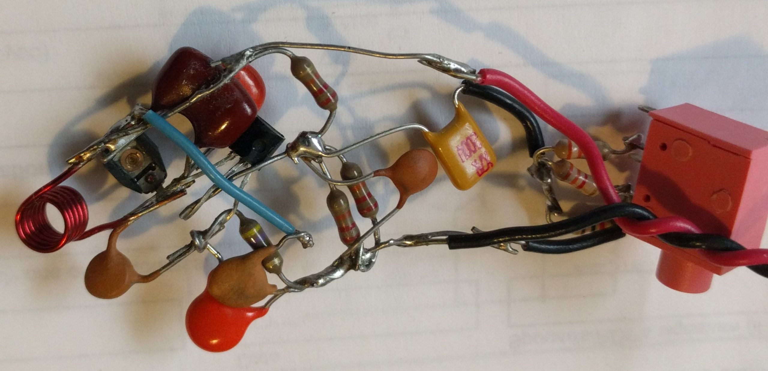
It uses no circuit board, but you can put it on a multiple hole prototyping circuit board. I don’t recommend building it on a Proto-Board because any movement will cause the contacts to change the frequency. So build it with real solder.
The + and Common Negative Supply Rails
I used 22 AWG bare solid copper wire for the supply rails, with a .01 uF ceramic capacitor for RF decoupling across the + to common negative. Some designs also use a 100 uF or larger electrolytic, which must be rated at or above the supply voltage. This should be used if the 6 volts is from the AC line AKA power supply. The supply voltage should be stable AKA regulated.
Audio Inputs Combined
Starting with the audio section, two 3.3k resistors go from each of the left and right pins on the earphone jack to a junction point; a 1k resistor goes from that point to common negative. These resistors combine the left and right channels and reduce their level to one-third. From that point to the base of the transistor is connected a 0.56 microfarad capacitor. If you use a polarized electrolytic, the positive should go towards the transistor.
The Base Bias
The base of the 2N3904 transistor has three 22k resistors and an RF bypass capacitor. There is a 22k resistor from the base to positive 6 volts. From the base to common negative there are two 22k resistors in parallel, and a .001 uF (1 nF or “102”) ceramic capacitor. The three 22k resistors could be lower, 10k should work.
The Emitter Circuit
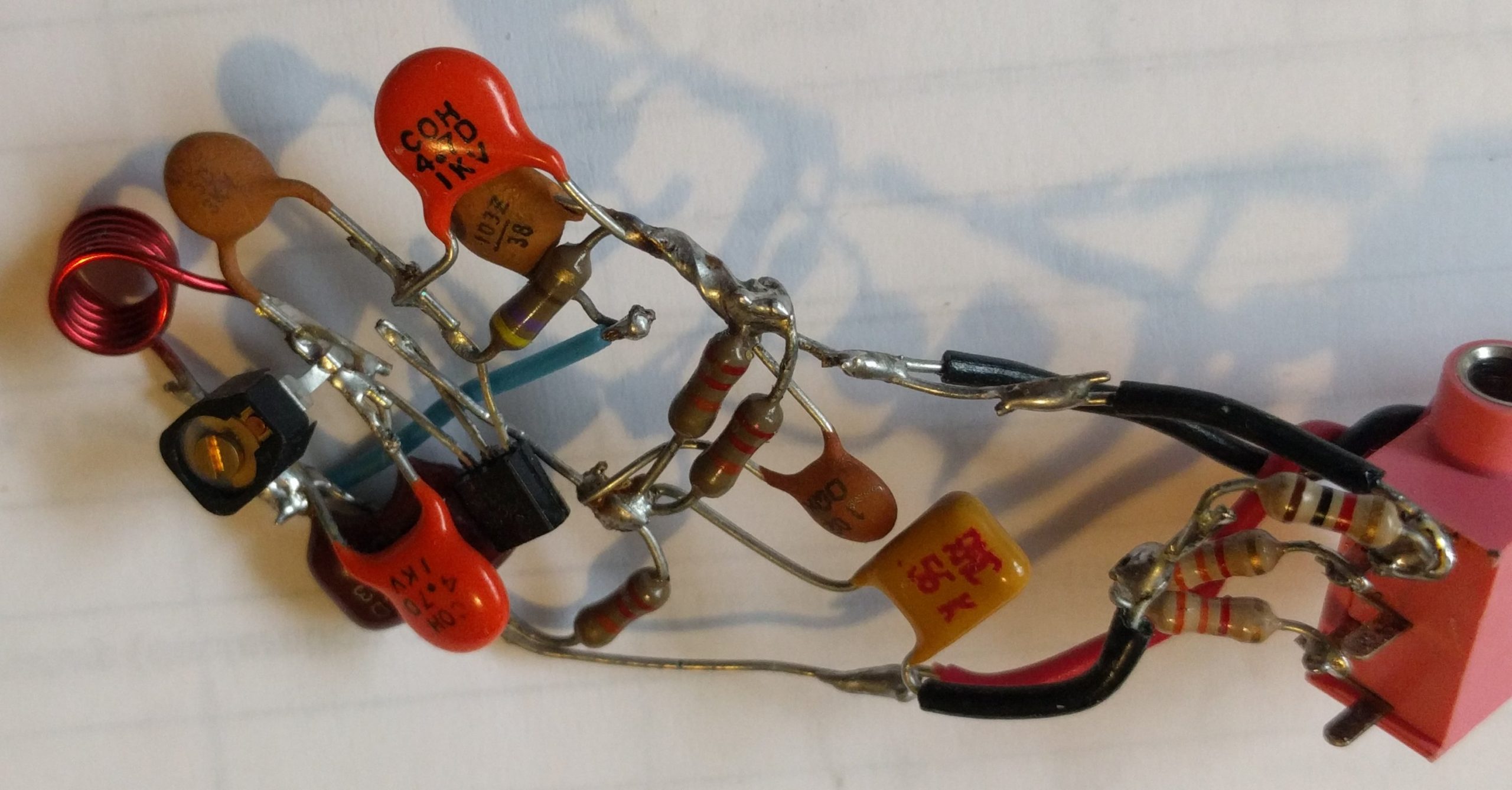
The emitter is connected to one lead of a 470 ohm resistor; the other resistor lead is connected to common negative. I connected an orange ceramic disc capacitor across this resistor. It’s labeled C0H 4.7D 1KV. The C0H (or C0G) indicates zero temperature coefficient. The 4.7 is the value: 4.7 picofarads. The D is the tolerance, but J or K should work okay. The 1KV is the voltage but anything should work. Some designs do not have this capacitor.
The Collector RF Circuit
The component leads of this area should be kept short. From the emitter to the collector is a ceramic disc capacitor, 5 picofarads and it can be the same as the 4.7 pF orange capacitor on the emitter.
The collector has four components – three capacitors and a coil – connecting it to the positive 6V. The brown capacitor is a 10 pF silver mica. There is an orange 4.7 pF same as the others across the brown cap. And a 0.5 to 5 pF trimmer capacitor across the brown capacitor. So the total adds up to 15.2 to 19.7 pF, which allows the circuit to be tuned to a channel on the low end of the FM band.
The RF Coil
The RF coil is 5-1/2 turns of 24 AWG enameled wire, wound on a 5mm or 0.2 inch wood skewer stick. The turns should be evenly spaced about half the wire thickness apart and the coil length should be 6mm long. This length can be squeezed or spread to give coarse tuning so the tuning capacitor covers the low part of the band. If the tuning capacitor can’t be used, then use a 20 or 18 pF total and tune the frequency with the coil. This coil is sensitive to vibrations, so it is better to put a tiny piece of paper towel inside the coil and drip some hot wax, glue or nail polish on it to hold the coil and prevent vibrations. Any copper wire can be used, even bare copper wire if the turns do not touch and the coil is coated with wax after tuning.