


I have often seen the conventional Joule Thief circuit used in situations where it is a poor choice – there could be better choices that would do the job.
The Joule Thief or blocking oscillator circuit transfers a low voltage, high current input to a higher voltage, lower current output, with a low efficiency and high losses. It’s a very simple circuit but has serious deficiencies. The typical Joule Thief’s input voltage will be 1.5VDC and the output load will be one LED (or 2 or more LEDs in parallel). The output voltage will be below 5VDC. The parts numbers I have given are for through hole transistors; if you want to use surface mount parts you can also find equivalents for them.
A Joule Thief with a 1k resistor and a small transistor, known as a ‘small signal’ transistor will put out up to 100 milliwatts to a standard 5mm diameter white or blue LED. The power can be reduced by increasing the base resistor from 1000 ohms to 3300, 4700, 10000, or more ohms, and the power to the LED will be reduced along with lower battery current and longer battery life.
If you use a 2N4401, PN2222A, BC337-25, the LED will get about 20 mA or 66 milliwatts with a fresh 1.5V battery. If you use a 2N3904, BC547 or similar transistor, expect to get less than 50 milliwatts, maybe only 30 or 40. The LED will not be as bright.
The Joule Thief circuit puts a heavy demand on the transistor for high current at very low voltage. It has a difficult job driving a single LED. If you want to drive a larger LED or two or more standard LEDs with more than 100 milliwatts, then you will need a higher current transistor specially made for switching very high current at very low voltage. Some common ones are 2SC2500, 2SD5041, KSD5041, ZTX1048A, NTE11, SS8050.
Solar Photovoltaic Cell And Other Low V Sources
One example of a low voltage source to which a Joule thief might be applied is a solar cell, or solar PV cell. The typical single solar cell puts out a maximum of about a half volt no load and somewhat lower, maybe 0.45 volts with a load. The typical silicon BJT (bipolar junction transistor) takes more than this to start, so using a regular transistor is not a solution. The best solution is to put at least two of the PV cells in series to get a higher voltage, with three or more giving the better efficiency. Even so, using a Joule Thief will lower the efficiency to about 50%, which is excessively high loss. It would be best to use several cells to get 3, 6, or more volts. For best efficiency it is best to do the conversion as close as possible to the cells and run the higher voltage to the load, which saves on the heavier wire that would otherwise be needed.
If additional cells are not possible, then the best way to up-convert a half volt is to use high current MOSFET transistors. A germanium transistor can be used to get enough voltage to start up the circuit, then the operation can be done with the MOSFETs.
Higher Supply Voltage
If the supply voltage is higher than 1.5V, then the Joule Thief may not be the best solution. The conventional Joule thief wastes about half of the power, so if you can use the supply voltage directly without the Joule Thief, it can double the battery life. If the supply voltage is above 3.5 volts, then the LED may be connected directly to the supply with just a simple current limiting resistor. This will save batteries, it will save electronics and the LED will do just as good a job of illumination. The best supply would have three 1.5V cells in series for 4.5V, or four rechargeable cells for 4.8 to 5 volts. Each LED would need a resistor that drops about 1V at 20 milliamps, or 50 ohms. Close values commonly available are 51 ohms or 47 ohms, 1/4 watt. When the battery voltage drops because of multiple LEDs connected to the same battery, this resistance may have to be reduced to maintain the 20 mA through the LEDs.
If the supply voltage is above about 6 or 7 volts and you use a coil with a 1 to 1 turns ratio, the supply voltage will be too high for the transistor. It is necessary to reduce the number of turns on the feedback winding to half the number of turns of the primary. The supply voltage can then be up to about 12 to 14 volts DC. But obviously the total voltage across the LED(s) would be higher than 3.3 volts, so to conform to the rule that the supply voltage must be less than the total voltage across the LED(s), there must be at least 5 LEDs in series. If this sounds confusing, just remember that if the supply voltage is greater than the total forward voltage of the LEDs, they will light up without the Joule Thief circuit, and since the LED(s) connect to the supply through the coil winding with very low resistance, excessively high current will flow through the LED(s), and this will damage or destroy the LED(s).
Alternative Circuits
Some JTers use a two transistor circuit that is mistakenly called a Joule Thief, but is more like an astable multivibrator, but the two transistors’ loads are not equal. The first transistor only drives the second transistor. This circuit does not have the coil voltage fed back to the base, so the voltage limitation of the emitter to base junction is not a concern. The one that uses a NPN for the output transistor and a PNP to drive the output is usually the better choice (scroll down to the 1-Cell Boost Circuit schematic here). But two NPNs work, it’s just that the NPN driver needs a low value resistor to supply the base drive current to the output transistor, where the PNP driver supplies the current, so no resistor is needed – but one is often used.
This circuit can be rearranged so that both transistors drive the coil, and the load is more evenly distributed. The coil uses the two windings of the conventional JT, but both of the transistors’ connectors are connected to them. An example of the schematic can be seen here. This one shows the extra turns on the coil, but it doesn’t have to have those, the rectifiers could be connected to the collectors.
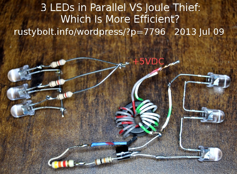 Update Jul 10 – I put together two LED circuits that both operate from a 5V supply. The first was three LEDs in parallel with 82 ohm current limiting resistor for each LED. The second was a Joule Thief with three white LEDs in series.
For the three in parallel the V drop across each LED was 3.34V, leaving 1.66V across the resistor. The LED current was 20 mA so 1.66V / 0.02 equals 83 ohms. I chose 82 ohm resistors, so the total current for the three LEDs was 60 milliamps. The efficiency of the three LEDs was 66.8 percent.
For the Joule Thief with the same LED current, the supply current was 76.8 mA, and the efficiency was 50 percent.
The conclusion is that the resistors are more efficient and use less current than the Joule Thief. The choice is obvious: the Joule Thief is not the best choice for this circuit.


My hope is to find (or fabricate) a current limiting device with the same basic footprint as the LED itself and equip each LED with one so that an infinit number of LEDs can be in the low voltage DC circuit, without having an issue with an overcurrent situation.
I would just use a resistor. With a few simple calculations, you could determine what resistance is needed for each color of the LEDs. For most color LEDs and a 5 volt power supply, a 100 ohm resistor would do the trick. It doesn’t sound all that efficient but when you do the calculations it comes out to about 70 percent efficient, which is better then a joule thief. If you really have to have a constant current, then you can buy a constant current diode. But inside they are just a JFET. You can do the same thing with any JFET, such as the MPF102. Just connect the gate to the source. Each JFET will be different, from 4 or 5 mA up to 20 or so mA, but you can select which ones are close to what you want. A single resistor or a single JFET is about the same size as a 5mm LED.
Another thing: if you’re concerned about size, there are LEDs with built-in resistors.
if i used these circuits to pull from very small, milli volts, and supply a single receptacle, how much voltage can i put out before the circuit is overloaded?
In short, could i take enough of these to charge a 12 volt battery?
Here is an example of a circuit. There were others on YouTube.
http://rustybolt.info/wordpress/?p=6677
I’m using MAX756-based circuits. Any tips on how to make it more efficient? I’ve noticed that removing the capacitor on the source side has no effect on output voltage of the chip.
The fresh battery has low internal resistance and the capacitor may have little effect. But when the battery gets discharged the internal resistance rises and the capacitor then helps filter out the high current pulses so there is less demand on the battery. I haven’t used that MAX chip, but with all high current devices the PC board layout and bypass capacitors are important. Check the data sheet and app notes for more info.
How did you calculate efficiency? Also, you did not mention how bright the leds were? Using a LUX meter would let you know wwhich was brighter. Your results are not conclusive.
Efficiency is the output power divided by the input power. Power is voltage times current. The input current can be measured but the output power assumes the LED drops 3.3 volts. A 1 ohm resistor in series with the LED is used to measure current.
I usually give my results, but I don’t usually claim they are conclusive . YMMV.
Hello,
Im a huge fan of the Joule thief circuit and thus would like to comment on the efficiency of the cycle. Its said here that the efficiency is very low; but i need to comment on that:
1. Stuff like LEDs donnot need continuous power supply and even increase performance when pulse driven
2. The Joule Thief circuit does not use a continuous current all the time, since the coil doesnt allow the same amount of current to pass through at any time. Due to the Power CYCLE INPUT versus the power CYCLE OUTPUT the efficiency is still very high. Also, the idea is not that the current is high (although ofc it has to be higher than output current). Efficiencies for duty cycle in an application appropriate for the joule thief are generally far over 90%, the only dissipating component is a resistor but that doesnt have any current flowing through at around 98% of the time