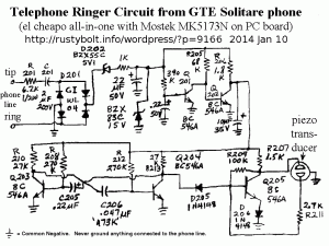
 This was drawn from the actual PC board of the telephone set. It was a cheap throwaway type telephone from long ago. Some of the part labels couldn’t be seen without removing the part. We will probably have a difficult time convincing the young kids that telephone sets had a cable that had to be plugged into a socket in the wall.
The incoming 90 volt ringer signal is rectified by D201 and if it’s greater than 5.2 volts it goes past D203 and charges the 22 uF 50V capacitor intul the BZX85C zener gets to 15V. Q202 has delayed turn-off for a fraction of a second and then the current goes through R206 to the circuits below. The 10 uF 35V capacitor charges up to the 15 volts. Q205 starts oscillating through the piezo transducer, and Q203 and Q204 switch on and off alternately, causing the transducer to sound like it is chirping or warbling.