


Click more than once to enlarge
I came across this .PDF a while back and I had one thing I wanted to show about it. The circuit is okay, but the 2 ohm current sensing resistor in series with the LED wastes about 25 percent of the power of the 1W LED. There is a simple way to reduce this, and that’s what I’d like to explain (see the schematic).
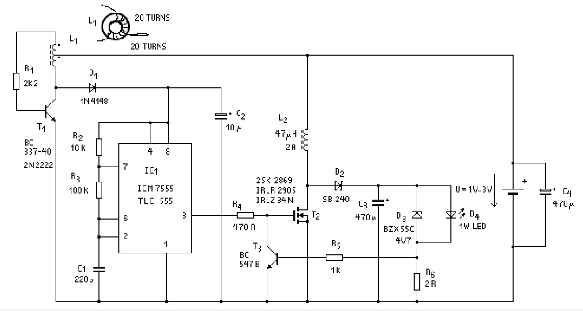
The circuit uses a MOSFET to boost the 1.5V input up to enough to drive the 1W LED. The MOSFET requires enough gate voltage to turn it fully on. For logic MOSFETs this could be 3 to 5v, but for a typical power MOSFET it might be 10 to 12V. I’m not sure what the gate voltage is for the other MOSFETs but the IRLZ34 requires 4 to 5V. Thus the Joule Thief circuit on the upper left must supply at least 5V to the 7555 chip (BTW, I would change C2 to a larger value, say 47 uF).
This circuit has LED current limiting. When the LED current gets up to about .33A (330 mA), the voltage across Rg gets up to about 0.66V, which turns on T3 and shunts the gate drive to negative. The MOSFET current drops and the LED current stabilizes at a fixed value of about .33 A. The problem is that the 0.66V drop across Rg wastes about .25W of power heating this resistor. The LED is only 1W, so 25 percent of the LED power is wasted in this resistor.
That seems easy to fix; reduce the resistor and compensate for the reduction in the voltage drop. The problem is that T3 requires about 0.66 V to turn on, so how do we change this? If we put a resistor from the base of T3 to the top of C2, and let it supply enough current to cause 0.4V across R5, then when the current through Rg causes it to drop 0.2V, the base of T3 will conduct and the circuit will start to limit the current. We can then reduce Rg to about 1/3 of 2 ohms or 0.67 ohm.
One thing that may be a problem is that the rectified voltage across C2 is not stable.
Other Improvements
Looking at the schematic, I see another improvement that would help reduce power waste. The output of the MOSFET goes through D2, a Schottky rectifier and then is filtered by C3, a 470 uF capacitor. This is not needed for the LED to light; apparently it is added to change the LED current from pulsating DC to straight DC, so that the voltage across Rg will be a DC voltage. But the Schottky diode has a half volt drop at the LED current, which is at least 0.33 A (it may be higher since the current is pulsed). Thus we could have a reduction in the amount of power wasted by the circuit by connecting the LED directly to the MOSFET and coil L2.
Then the voltage across Rg becomes pulsed, so we have to find a way to get the rest of the circuit (R5 and T3) working with pulsed DC. The LED is a diode so it rectifies the current from the coil L2, so the voltage across Rg, although pulsed, is already DC. If we add a resistor and capacitor (low pass filter) between Rg and R5, the right end of R5 should have filtered DC, without pulses. But will the DC voltage be the same as the original circuit, with 0.33A through the LED? I’m not sure.
Would it be possible to put a large capacitor across Rg to filter out the pulses? The value of Rg is very low, only 2 ohms or less. I haven’t checked to find out what the frequency of the 7555 is, but for now I’ll assume it’s 50 kHz. The capacitor has to have a reactance of much less than 2 ohms at 50 kHz; typically ten times less or 0.2 ohms. It will take a large capacitor to give this low reactance, and it will have to be a low ESR capacitor. I went to this online calculator and found that 22 uF was low enough, but from past experience with capacitors, I would go for a much larger value, 100 or more uF, and probably use a 1000 uF 10V low ESR capacitor from a switching power supply. Then what will the AC and DC voltage across the capacitor be? Hopefully the AC voltage will be only millivolts, thanks to the capacitor.
One problem that occurs is when we try to measure pulsating DC with a DMM. This is because most digital multimeters do not register true RMS voltage, and we are dealing with pulsing DC that does not act like straight DC from a battery. These DMMs usually show average voltage. And that’s not the same as DC with pulses. If you put the DMM across the transistor of a Joule Thief, with the LED lit brightly, it will typically measure 1.5VDC, which is the battery voltage. But we know the voltage has to be higher because the LED is lit. The conclusion we have to make is that the DMM does not read the actual value of the DC plus AC.
I my earlier blog I made a similar circuit. But I used the output of the Joule Thief to drive the MOSFET, and saved parts by not using the 555.


