 Often a project has to be turned on or off by a switch that has only one set of contacts, and those contacts are normally closed. When the project needs to be activated, the switch has to go from normally closed to open. One common example of this is a window or door switch that is magnetically operated. When the window or door is closed, the magnet pulls the switch closed, so most of the time the switch conducts current. but you want the switch to activate the project – alarm for example – when the door or window is opened.
To make matters more complicated the alarm is battery operated, so you want it to draw very little current when the windows and doors are closed. So somehow you need to invert the switch’s action, but it has to me done with a very tiny current flowing through the switch most of the time. This is when you need to use a few transistors to invert the switch’s current.
Operation
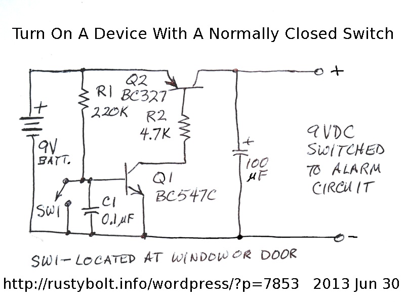
The switch Sw1 is located at the door or window. If the a;arm is hard wired then there will be a two conductor cable from the switch to the circuit. Sometimes the alarm is operated remotely through a radio frequency, so the switch would be on or very close to the transmitter. The wire from the switch to the circuit may pick up AC hum and radio frequency interference, so the C1 capacitor bypasses these frequencies to the negative, thus preventing false turn-on.
The R1 resistor furnishes a very small current, only about 40 microamps, to the switch while it is closed. When the switch is closed, the voltage at the base of Q1 will be near or at zero volts. No current will flow through Q1, and thus no current will flow through Q2, and there is no 9V at the output of the circuit.
When the switch is opened, the current from R1 will then be diverted through the base of Q1, turning it on. The current gain of Q1 may be a few hundred, so the current from the collector to emitter may be a few hundred times 40 microamps, or several milliamps. The collector voltage of Q1 drops to near zero, and nearly 9 volts is across R2. R2 will allow about 2 milliamps to flow through the base to emitter junction of Q2, turning it fully on. The full 9V is then available at the output. The gain of Q2 may be more than 100, so at least 100 mA should be available at the output. But 9V batteries don’t have the ability to supply heavy current, so a more typical load might be 40 mA maximum.
This same circuit can be applied to bigger batteries with more current, but higher power transistors may have to be used. The Q2 is critical, it has to be turned fully on so that there is very little voltage drop and very low power dissipation.
I my case, I am going to use a switch to remotely tell me if the garage door is open. I thought that I could put the switch at the point where the door stops when it’s fully open. This can then be a simple normally open switch, closed when the door is fully open. But what happens if the door is opened part way, but never reaches the end of its travel? The door would be open but there would be no indication of being open. Therefore I decided that I should put the switch at the bottom of the door, where it will be activated as soon as the door is slightly opened. The normally open switch is held closed by the closed door, and then opens as soon as the door opens. This is why I had to come up with the circuit I have described.