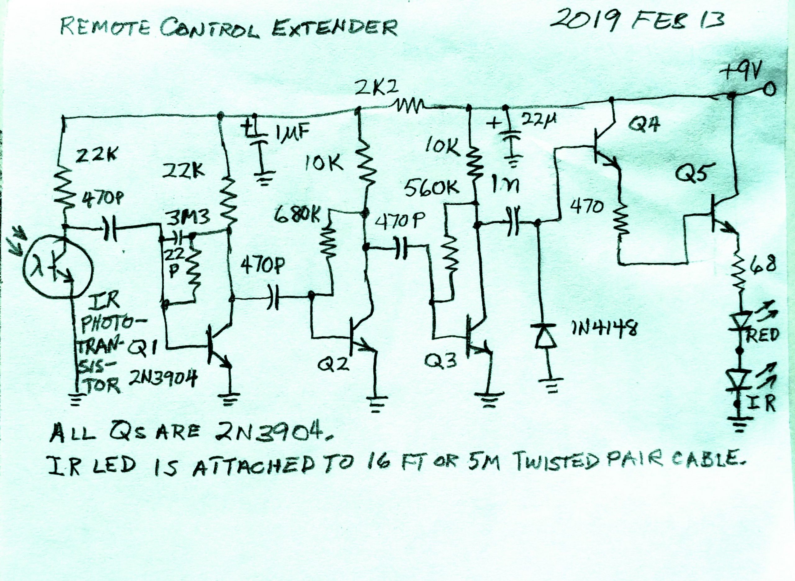
Many years ago I built this remote control extender. I had an old RCA TV that used an infrared remote control that was not digital, it put out unmodulated carrier waves of frequencies in the 34 to 40 kHz range. These are much different than the digital remote controls we have today, which are designed to demodulate pulses. So my remote control had to work with both digital from my VCR remote and unmodulated CW from the TV.
I built this circuit to be a simple analog amplifier of three stages, driving a class C Darlington output that’s connected as an emitter follower to drive both the IR LED and the red LED.
It works very well, but the idle current is more than a milliamp, which would soon use up a 9 volt battery. So what the circuit needs is to have a reduction of its idle current. The darlington LED driver stage is Class C and draws no current as long as it’s idle. The three low level amplifier stages must be on all the time so they’re the ones that have to be very low idle current. I plan to reduce the idle current to below 0.25 mA, maybe to 100 microamps.
The first two stages need only 3 to 5 volts so the 2.2k dropping resistor in the supply line can be increased to 10k or more. After that, the Q3 collector load resistor could be increased from 10k to 22k or more, maybe up to 100k. The base bias resistor will have to be increased from 560k to a few megohms.
