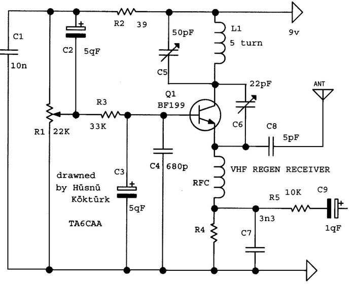
After I unsoldered the parts from my failed ‘noisy regenerative receiver’ circuit, I decided to build a more conventional regenerative receiver, one that uses a single transistor for the regenerative stage. I chose the circuit from a website that I had found, and saved the schematic. But I forgot to document the URL of the website. So I’ve attached the schematic which has the author’s name and ham call letters to identify it.
I used the following values for the parts.
C1 100 nF
C2 not used
C3 4.7 uF
C4 1000 pF
C5 27 pF fixed, 4 to 14 pF var. cap in parallel.
C6 25 pF mica variable capacitor
C7 two 2.2 nF in parallel.
C8 5 pF variable capacitor set to max
C9 not needed, already in the audio amp
R1 10k, 25 turn trimpot
R2 0 ohms (not used)
R3 44k – two 22k in series
R4 no value given, used 1k in series with a 5k pot, giving 1k to 6k
R5 10k
L1 14 turns 20 AWG on 3/8 in. diam. wood dowel – about 0.8 uH.
RFC1 33 uH RF bead with several turns threaded through the center hole
Q1 I used a C9018 VHF transistor.
I reused my amplifier and earphone from the nonworking regenerative receiver. The supply is a three AA cell holder, so fresh cells will give a bit more than 4.5 volts.
I got noise from the regenerative circuit as soon as I powered it up. With a little tweaking, I tuned it, and got noise but received no communications. I did hear bursts of RF coming from my cell phone. The antenna is only about 7 inches long. I think the receiving frequency is not in the CB band. My dip meter showed the coil as resonating at about 27 MHz. I guess I’ll have to make a transmitter that puts out a known frequency in the 27 MHz band. I looked for some schematics of VFOs that hams build and I found one that is supposed to be very stable if it is built properly.
Update Dec 7 – I mounted most of the pieces on a piece of plywood, and put a piece of sheet metal on it for a front panel. I got the Batteries, audio amp and volume pot mounted. I drilled a hole in the plywood that is the size of the dowel that holds the coil, and I can press the dowel into the hole so that it fits snugly. I have to rearrange some of the parts so they aren’t in the way. The RF part is sensitive to movement, so this ‘breadboard’ should help a lot in making it more stable. I measured the total battery drain at about 2.5 mA.
I changed the fixed resistor R4 to 1k and a 5k pot in series and mounted the pot on the front panel. I get hiss, but I still haven’t received any signals. After adjustments my dip meter said the coil was resonating at about 27 MHz, but the meter isn’t accurate and is probably off a bit. When the dip meter is on, it quiets the hiss, so I guess that means the regenerative circuit is doing something.
I have been looking at other regen schematics, and I found that the ones that use a JFET do not need a diode detector, but the others that use a BJT have a diode as the detector. Except for the one I’m experimenting with, which is missing the diode. I think I’m going to have to add a diode somewhere, and I’ll have to do some experimenting to find out where.
Update 2017-01-22 I’m building another FM regenerative receiver, see here.

I saw this schematic in the TRAC Turkish magazine at 1970