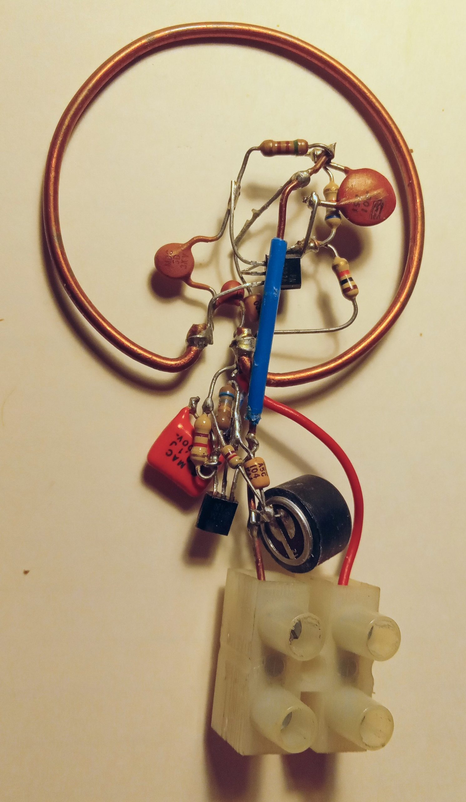
I think I built one of these years ago but it must be buried in a box somewhere, probably in a pile of boxes in the garage. It’s a FM microphone transmitter, of which I have several, built from kits and from scratch. But this one was unique in that I built it with a coil of a single turn of heavy wire. I used a piece of 12 or 14 AWG bare solid house wire, the kind found inside of the walls. The insulation was stripped off and I bent it into a circle about 40 to 45 mm or 1-9/16 to 1-3/4 inches diameter. I just arbitrarily chose a length of wire and bent it, with the ends sticking out about 3/8 inch so that I could solder the other components onto it.
But this time I decided to try calculating the size of the wire from a formula given in Illustrated Handbook of Electronic Tables… by Ludwig on P. 206. I tried it with several different radiuses, but I used 0.08 inch – the diameter of the wire – for the coil length of all of them. The results I got were not close to the results I had obtained experimentally. The only thing I can think of that might be causing this is that the algebraic calculations I was doing were not the same as what is shown in the formula. It’s possible that the formula is incorrect. I’m going to have to try some other manuals to see if they agree.
I did calculations for a coil of 0.1 microhenry and a diameter of 1.8 inches which is a radius of 0.9 inches. The answer came to 1.048 turns. But I have already cut and bent a piece of wire into a circular coil with almost but not quite a single turn and a diameter of 1.8 inches and it measures 0.098 microhenry or 98 nanohenrys. The formula gives a somewhat close answer, but it is reliably high from this and a few other calculations that I did. This is acceptable as long as one knows that the calculations will be off a certain amount, so that it can be compensated.
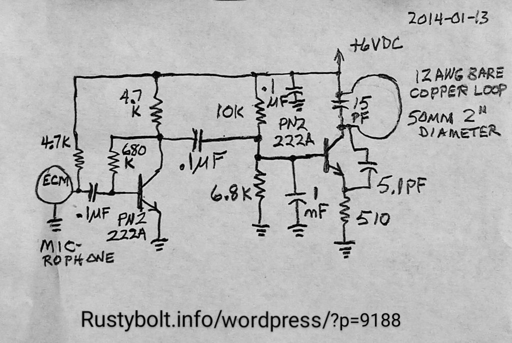
I built the transmitter using the loop of 12 AWG bare copper wire approximately 1.95 inches in diameter. The oscillator transistor is a PN2222A, and the audio amp is also a PN2222A. The loop has a 15 pF ceramic capacitor across it to resonate at the low end of the FM band around 89 MHz. This will have to be adjusted for the various components used, especially the transistor.
The emitter resistor for the RF oscillator determines the output power. I used a 510 ohm resistor, which I a bit higher than the typical 330 to 470 ohms. The emitter current is about 2 MA, which is less than 10 milliwatts total power with fresh batteries. Less than a third of that gets out as RF, so this circuit is just ‘flea power’ compared to other wireless microphones.
The audio transistor amplifies the electret condenser microphone (round black thing at the bottom). The battery pack is three AAA cells in series for 4.5 volts. If rechargeable cells are used, there should be four, totaling 5 V.
I took the ‘bug’ out to an open field and propped it upright on a pile of dirt so the coil (or ring) was above the rest of the circuit. I used a cheap portable radio with an extra length of wire added to the whip antenna to make it about 30 inches. I could get the signal up to about 100 to 120 feet or 30 to 36 meters before it faded out. But another station was on a nearby frequency and it bled through when the bug got weak. This was around 90 MHz, at the low end of the FM band. I might have been able to receive it farther away if I had a better radio and if it had been farther away from a strong station. But in a large urban area it’s nearly impossible to find a frequency that is not already being used by a strong FM station.