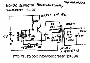
I got this schematic out of an old book, old enough to still use Germanium transistors. It uses some overvoltage protection diodes on the base. The 9V Zener and capacitor also look like some form of overvoltage protection. This would have to be modified for a silicon transistor.
The battery says 5V, so I assume that it’s four 1.25V NiCd rechargeable cells. Makes sense since the current draw is heavy when this thing is running. The emitter winding is 18 AWG heavy gauge wire and that gives you another indication of how high the current is. I will have to try to find the Arnold core online. I’m guessing that it’s not a toroid, probably because it would be difficult to wind the 860 turn secondary onto a toroid.
Also, notice that there are dots next to the starting end of the windings. This means that each winding should be connected as shown, and if it is not, the circuit won’t work. With the two windings on the left side, this is true. With the 860 turn winding, if it is connected backwards, the output may not be as high a voltage or current, but it may put out some power. In this case, it would be best to try it both ways and find out which puts out the most power.
One thing that I would add to this circuit is a large bypass capacitor across the battery. I would use a 470 or 1000 uF electrolytic capacitor.