


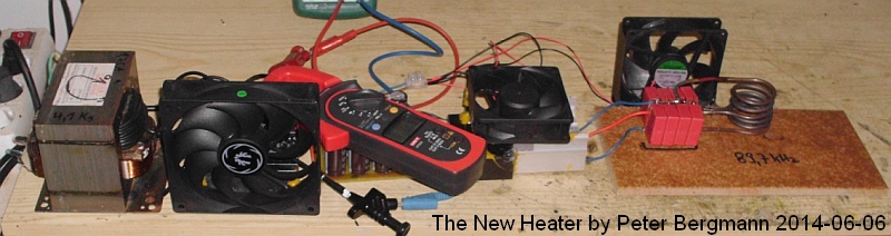
 Wow! Red hot metal in just a few tens of seconds! Peter has been experimenting with a MOT ( microwave oven transformer) with a rewound secondary that puts out 26 volts at up to 1000 watts. He fed this into an 80v, 35 amp bridge rectifier and a bank of 4700 uF at 35 volt capacitors to filter the output the DC.
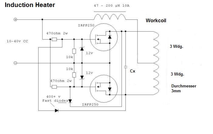 The circuit he used is similar to the one here. The author called it a Royer oscillator, but I’ve never heard that term before. This is a simple circuit that anyone could build. However the coil and capacitor bank make a tuned circuit that has to handle a large amount of power, which puts high stress on the heavy coil wire and especially the capacitors. That is why the author recommended using special types of capacitors, which are able to handle the stress and heat.
The circuit is dealing with hundreds of watts, at times close to 1kW. The full wave bridge rectifier and MOSFETs are mounted on heat sinks which are needed to keep them cool.They have a fan to increase the air flow and hence keep them cooler. Bigger heat sinks are better.
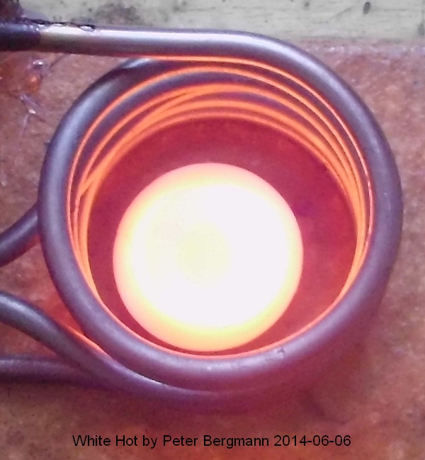 The sight of a crucible of metal melting is a sight to behold. You can cast your own toys or parts, or anneal parts or make alloys. But just having a simple circuit that makes heat by induction is really cool. And it’s relatively cheap and easy to build.
The MOT (microwave oven transformer) is free, salvaged from a non-working microwave oven. The high voltage (CAUTION!) secondary has to be removed and a new secondary wound in its place with heavy wire. This could be as few as 25 turns. Peter said his puts out 26 volts.
The heat sinks may cost a bit, but a large sheet of 3/16 or 5mm thick aluminum can be used. Heavy copper wire can be bought from the Big Box hardware stores. Fans can be salvaged from an old PC but have to be cleaned and tested to see if they are in working shape. The tank capacitors (big red ones connected to the coil) may cost quite a bit, and it’s best to get good quality ones and not cut corners. The MOSFETs were IRFP250, and cost a few dollars apiece. Any parts can be ordered from Mouser.com. Some may be available at the local electronics store. As with any project, the first thing that must be done is to acquire all of the parts. Then you can begin the assembly. There is no sense in spending a lot of time getting part way through a project to find that you are not able to obtain a component.
Some helpful information
I measured five inductors that I salvaged from PC SMPS power supplies. They all have yellow cores with the bottom painted white and they all have about 25 turns of heavy magnet wire. The size in mm is the outside diameter of the core. The turns count may be + or – a turn or 2.
20mm, 25 turns 30 uH
24mm, 25 turns 47 uH
27mm, 24 turns 56 uH
27mm, 24 turns 57 uH
The 27mm seem to be very common. These cores measured 10mm height. Later I measured some more and all of them were about 56 uH. Some had multiple windings of various thickness enameled wire. The windings of heavier wire with fewer turns measured about 9 uH.


hi first ı have to said ı dont know good english and ı have to something.
ı dont know maybe u dont help me or u do
ı wanna this induction oven all project and component names diode bla bla bla. thanks for help
I’m sorry, but you must ask the author of this induction oven. I did not build it and I have never built one.